5742639-JIM-C-0220
10 Johnson Controls Ducted Systems
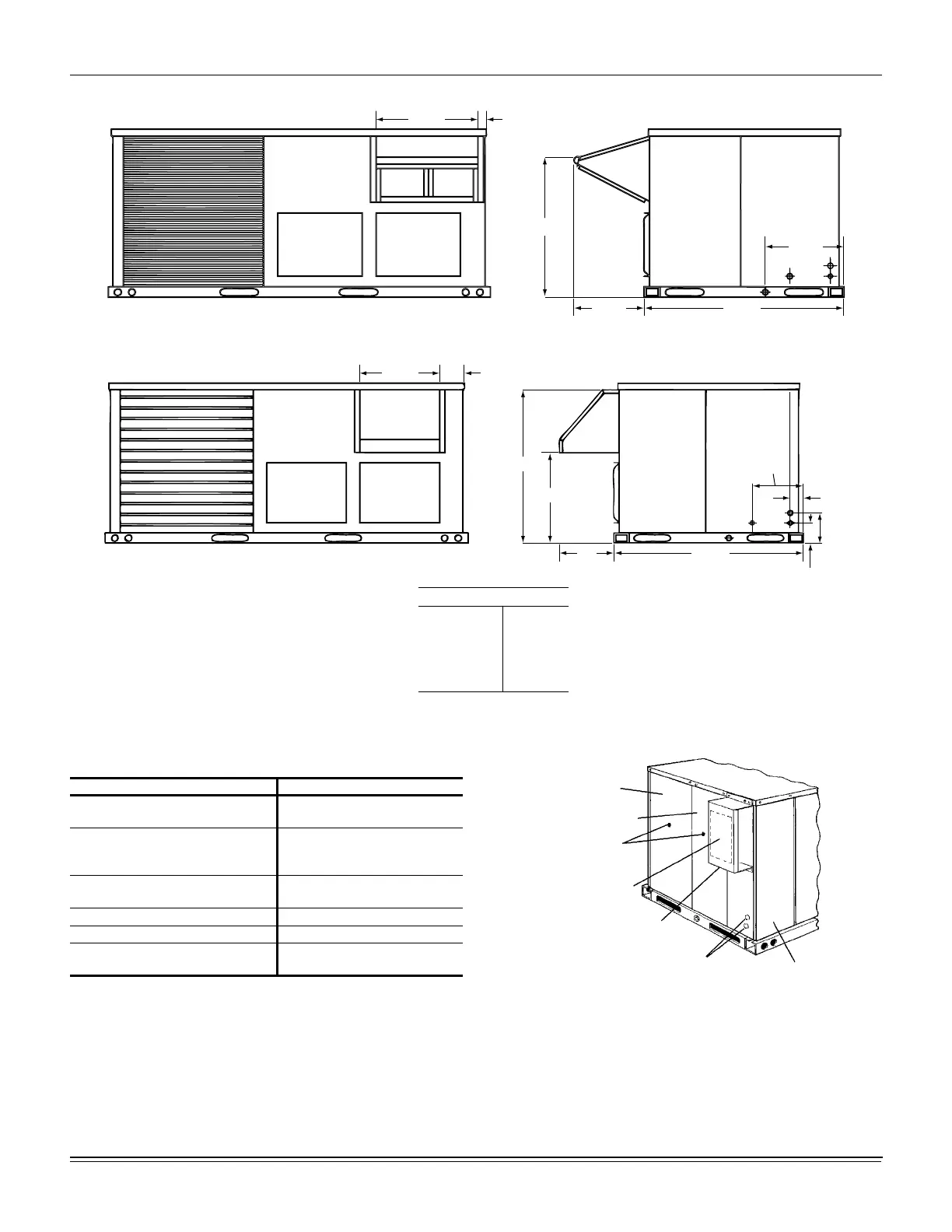
Figure 7: J03 through A6ZE Fixed Outdoor Air Motorized Damper Rain Hood Physical Dimensions
Figure 8: J03 through A6ZE Disconnect Location
Detail “A”
27-1/2
27-1/2
1-5/8
19-1/2 44-7/8
19-3/4
Rear View
Detail “B”
Dimension “A”
Fixed
Outdoor
Air Damper
12
16-1/2
Motorized
Damper
LH End View
27-1/2
27-1/2
7-1/4
“A” 44-7/8
4-3/8
8-1/4
3-1/2
10-1/4
19-1/8
Table 4: J03 through A6ZE Unit Clearances
Location Clearance
Front
24” (Cooling/Electric Heat)
32” (Gas Heat)
Rear
12” (Less Economizer)
36” (With Economizer or Fixed
Air/Motorized Damper)
Left Side (Filter Access)
24” (Less Economizer)
36” (With Economizer)
Right Side (Cond. Coil) 24”
Below Unit
1
1. Units may be installed on combustible floors made from
wood or class A, B, or C roof covering material.
0”
Above Unit
2
2. Units must be installed outdoors. Overhanging structures
or shrubs should not obstruct condenser air discharge
outlet.
72” (For
Condenser Air Discharge)
Disconnect Switch Location
and Motor Access Panel for
Unit with “Belt-Drive” Option
Control Box Access
A,B
Wiring Entry
(See Detail “B”)
Mounting Bracket for
Disconnect Switch
(Field Supplied)
Field-Supplied Disconnect
Switch Location
Blower Motor Access
Filter Access
Dot Plugs

 Loading...


