5742639-JIM-C-0220
Johnson Controls Ducted Systems 15
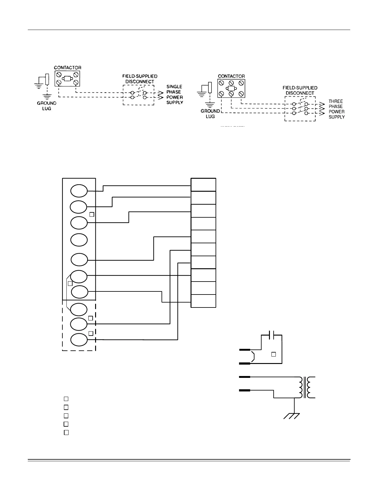
Typical Field Power and Control Wiring
Typical Power Wiring
Typical Cool/Heat Control Wiring (Simplicity Lite J03 through 05ZE)
Figure 13: Typical Field Power and Simplicity Lite Control Wiring
REFER TO THE ELECTRICAL DATA
TABLES TO SIZE THE DISCONNECT
SWITCH, OVERCURRENT PROTEC-
TION AND WIRING.
OCC
C
RC
G
Y2
Y1
W2
W1
X
R
THERMOSTAT
TERMINALS
CONTROL
TERMINAL
BLOCK
TERMINALS ON A
LIMITED NUMBER
OF THERMOSTATS
1
4
3
1
2
4
Second stageŚĞĂƟŶŐŶot required on single stage heĂƟŶg units.
Jumper is required if there is no Smoke Detector circuit.
Jumper is required for any coŵďŝŶĂƟŽŶ of R, RC, or RH.
5
5
OCC is an output from the thermostat to indicate the Occupied ĐŽŶĚŝƟon.
X is an input to the thermostat to display Error Status condiƟons.
3
W2
Y1
G
OCC
Y2
X
R
SD-24
C
W1
C
SD
SD
R
Jumper
Smoke
Detector
24 VAC
Class 2
2

 Loading...


