5742639-JIM-C-0220
Johnson Controls Ducted Systems 57
Checking Gas Input
Natural Gas
1. Turn off all other gas appliances connected to the gas meter.
2. With the furnace turned on, measure the time needed for
one revolution of the hand on the smallest dial on the
meter. A typical gas meter usually has a 1/2 or a 1 cubic
foot test dial.
3. Using the number of seconds for each revolution and the
size of the test dial increment, find the cubic feet of gas
consumed per hour from the Gas Rate - Cubic Feet Per
Hour (Table 26).
If the actual input is not within 5% of the furnace rating (with
allowance being made for the permissible range of the regulator
setting), replace the orifice spuds with spuds of the proper size.
NOTE: To find the Btu input, multiply the number of cubic feet
of gas consumed per hour by the Btu content of the gas
in your particular locality (contact your gas company for
this information - it varies widely from city to city.)
Adjustment Of Temperature Rise
The temperature rise (or temperature difference between the
return air and the heated air from the furnace) must lie within
the range shown on the rating plate and the data in the Gas
Heat Application Table 11.
After the temperature rise has been determined, the cfm can be
calculated as follows:
After about 20 minutes of operation, determine the furnace
temperature rise. Take readings of both the return air and the
heated air in the ducts (about six feet from the furnace) where
they will not be affected by radiant heat. Increase
the blower
cfm to decrease the temperature rise; decrease the blower cfm
to increase
the rise. Refer to the In Door Blower Specification
Table 18.
Start Up For Units Equipped for FER
This section applies to single phase gas heat only.
Direct Drive
Direct drive FER units come from the factory with the following
three leads that lead to the indoor motor.
• A yellow cooling lead
• A red heating lead
• A white, fan only lead
Each lead is put on a different tap on the motor and provides
different speeds. The leads are set on default taps from the
factory. See the wiring diagrams for details on factory default
speeds. During installation, you may need to move the leads to
different taps depending on the airflow and static requirements
of the application.
NOTE: During installation, the tap chosen for the heating
speed must produce a temperature rise that lies within
the rise range stated on the rating plate and the data in
Table 11.
Belt Drive
Belt drive FER units come with a VFD that provides heating,
cooling, and fan only speeds. The units are controlled by a 2-10
vdc output from the Smart Equipment™ control to the supply
fan VFD.
You may need to adjust the speeds for specific applications as
factory defaults may not always be suitable. To make airflow
changes, adjust the variable pitch sheave pulley. If pulley
adjustments fail to achieve the required airflow, you may need
to adjust the factory default speed settings for the Smart
Equipment™ control, see Adjusting the fan speed percentages.
NOTE: During installation, the speed chosen for the heating
speed must produce a temperature rise that lies within
the rise range stated on the rating plate and the data in
Table 11.
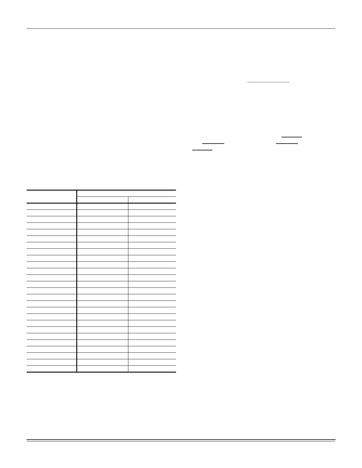
Table 26: Gas Rate-Cubit Feet per Hour
1
1. By actual measurement, it takes 38 seconds for the hand on
the 1-cubic foot dial to make a revolution with a 100,000 Btuh
furnace running. Using this information, located 38 seconds
in the first column in the table above. Read across to the
column headed “1 Cubic Foot”, where you will see that 95
cubic feet of gas per hour are consumed by the furnace at
that rate. Multiply 95 X 1050 (the Btu rating of the gas
obtained from the local gas company). The result is 99,750
Btuh, which is close to the 100,000 Btuh rating of the furnace.
Seconds for
One Rev.
Size of Test Dial
1/2 cu. ft. 1 cu. ft.
10 180 360
12 150 300
14 129 257
16 113 225
18 100 200
20 90 180
22 82 164
24 75 150
26 69 138
28 64 129
30 60 120
32 56 113
34 53 106
36 50 100
38 47 95
40 45 90
42 43 86
44 41 82
46 39 78
48 37 75
50 36 72
52 35 69
54 34 67
56 32 64
58 31 62
60 30 60
CFM
Btuh Input x 0.8
=
108..xFTempRise
o

 Loading...


