5742639-JIM-C-0220
66 Johnson Controls Ducted Systems
The control flashes three times as it writes a 30 second
delay ON and a 90 second delay OFF to the program.
• Gas Heat Option #2 - Press the COMM SETUP and
TEST RESET buttons simultaneously and then release.
The control flashes four times as it writes a 30 second
delay ON and a 180 second delay OFF to the program.
• Electric Heat - Press and release the COMM SETUP and
LAST ERROR buttons at the same time. The control
flashes twice on the LED as the control writes a 0 second
ON and a 30 second OFF fan delay to the control’s
program memory.
Smart Equipment™ Control Board
Navigation Components
The following components are needed to access the control
points in the Smart Equipment™ control. Installation and
operation guides are available from your equipment dealer or
distributor.
1. Local LCD on Unit Control Board.
2. Mobile Access Portal (MAP) Gateway (Portable).
• Source 1 P/N S1-JC-MAP1810-OP
3. MAP Gateway Quick Start Guide P/N 24-10737-16
4. MAP Gateway Instruction P/N 24-10737-8
For more information on the Smart Equipment™ unit control board
navigation, refer to the Smart Equipment™ Quick Start Guide.
NOTE: For more in-depth sequence of operation of the Smart
Equipment™ control, refer to the Smart Equipment™
Controls Sequence of Operation Overview LIT-
12011950.
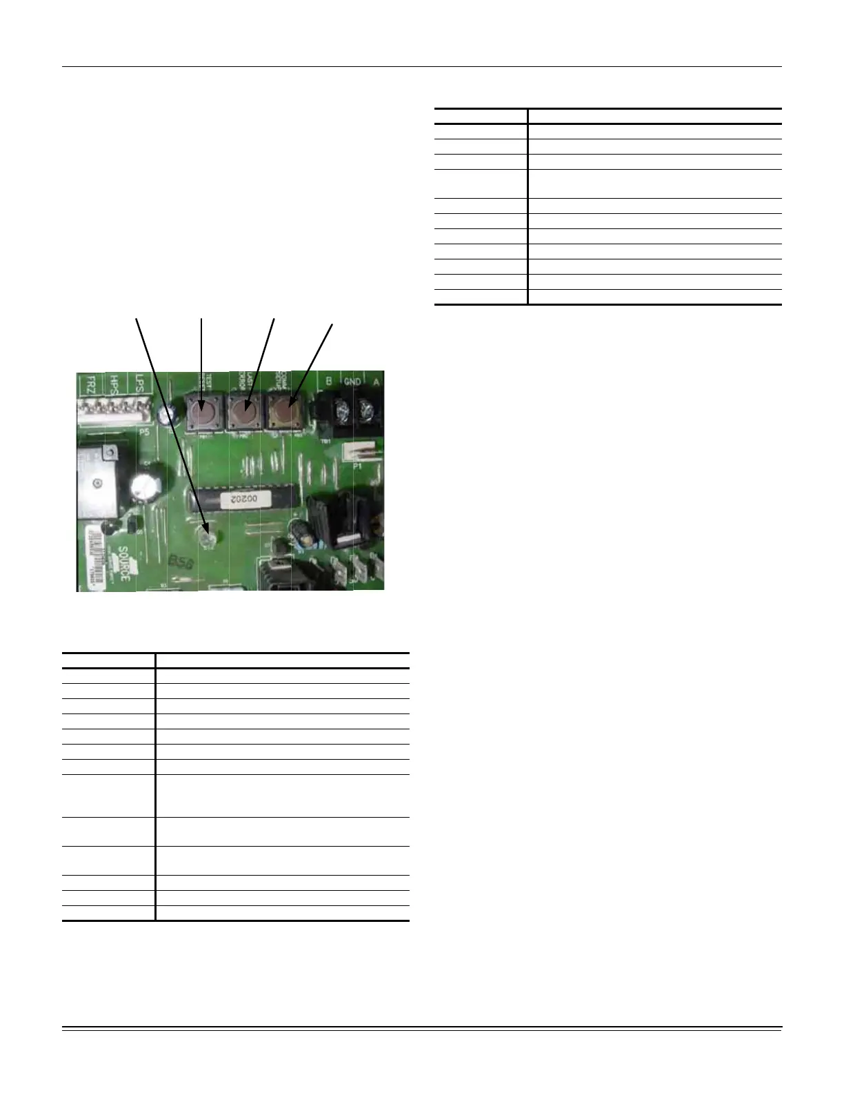
Figure 28: Unit Control Board
Table 32: Unit Control Board Flash Codes
Flash Code Description
On Steady Control Failure - Replace Control
Heart Beat Normal Operation
1 Flash Not Applicable
2 Flashes Control waiting ASCD
1
1. These flash codes do not represent alarms.
3 Flashes HPS1 - Compressor Lock out
5 Flashes LPS1 - Compressor Lock out
7 Flashes FS1 - Compressor Lock out
9 Flashes
Ignition Control Locked Out/
Ignition Control Failure / Limit Switch Trip / No
Jumper Plug in Heat Section
10 Flashes
Compressors Locked Out On Low
Outdoor Air Temperature
1
11 Flashes
Compressors Locked Out Because The
Economizer Is Using Free Cooling
1
13 Flashes Compressor Held Off Due To Low Voltage
1
14 Flashes EEPROM Storage Failure (Control Failure)
OFF No Power or Control Failure
Comm Setup
Button
Last Error
Button
Test Reset
Button
Control Board
LED
Table 33: Ignition Control Board Flash Codes
Flash Code Description
Heart Beat Normal Operation
1 Flash Not Applicable
2 Flashes Pressure / Centrifugal Switch Open with Inducer On
3 Flashes
Pressure / Centrifugal Switch Closed with Inducer
Off
4 Flashes Not Applicable
5 Flashes Lock Out From Too Many Flame Losses
6 Flashes High Temperature Switch Open (Primary or Aux.)
7 Flashes Rollout Switch Open
8 Flashes Flame Present With Gas Off
9 Flashes Gas Valve Stuck Off or On
10 Flashes Flame Sense Circuit Failure

 Loading...


