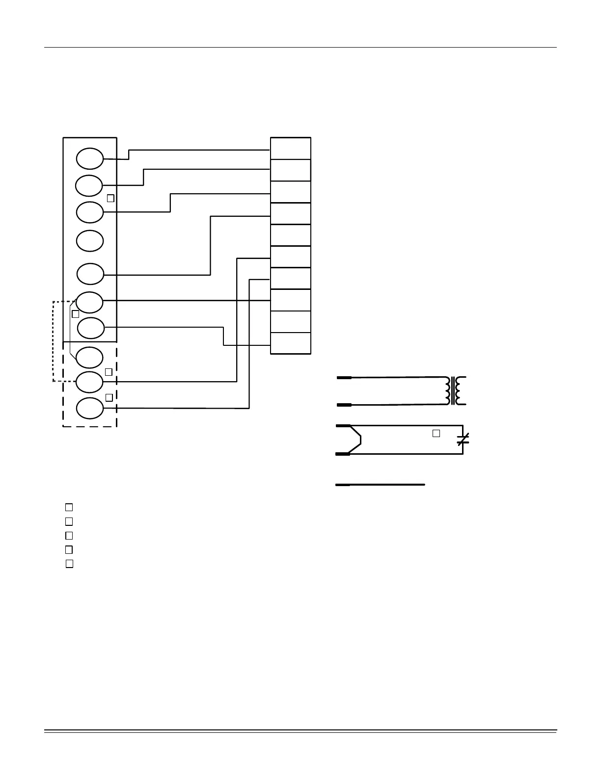
OCC
C
RC
G
Y2
Y1
W2
W1
X
R
THERMOSTAT
TERMINALS
CONTROL
TERMINAL
BLOCK
TERMINALS ON A
LIMITED NUMBER
OF THERMOSTATS
1
4
3
1
2
4
Second stageŚĞĂƟŶŐŶot required on single stage heĂƟŶg units.
Jumper is required if there is no Smoke Detector circuit.
Jumper is required for any coŵďŝŶĂƟŽŶ of R, RC, or RH.
5
5
OCC is an output from the thermostat to indicate the Occupied ĐŽŶĚŝƟon.
X is an input to the thermostat to display Error Status condiƟons.
3
W2
Y1
G
OCC
Y2
X
R
SD-24
C
W1
2
24V
C
24 VAC
Class 2
SD-24
Jumper Located on Harness
Smoke
Detector
SD-R
24V Output
R
(If No Smoke Detector)
(If Smoke Detector Is Used)
R~Occ Jumper:
Smart Equipment Control boards come from the
factory with a jumper wire between R and OCC
terminals on the thermostat terminal strip. Failure
to remove this jumper will place the unit into the
Occupied mode no matter what the occupancy
demand is from the thermostat or EMS system.
To allow Thermostat or EMS control of the
Occupied mode for the unit, this jumper must be
removed during commissioning.

 Loading...


