5742639-JIM-C-0220
56 Johnson Controls Ducted Systems
2. Check for correct manifold gas pressures. See “Checking
Gas Input” on page 57.
3. Check the supply gas pressure. It must be within the limits
shown on rating nameplate. Supply pressure should be
checked with all gas appliances in the building at full fire. At
no time should the standby gas line pressure exceed 13",
nor the operating pressure drop below 5.0" for natural gas
units. If gas pressure is outside these limits, contact the
local gas utility for corrective action.
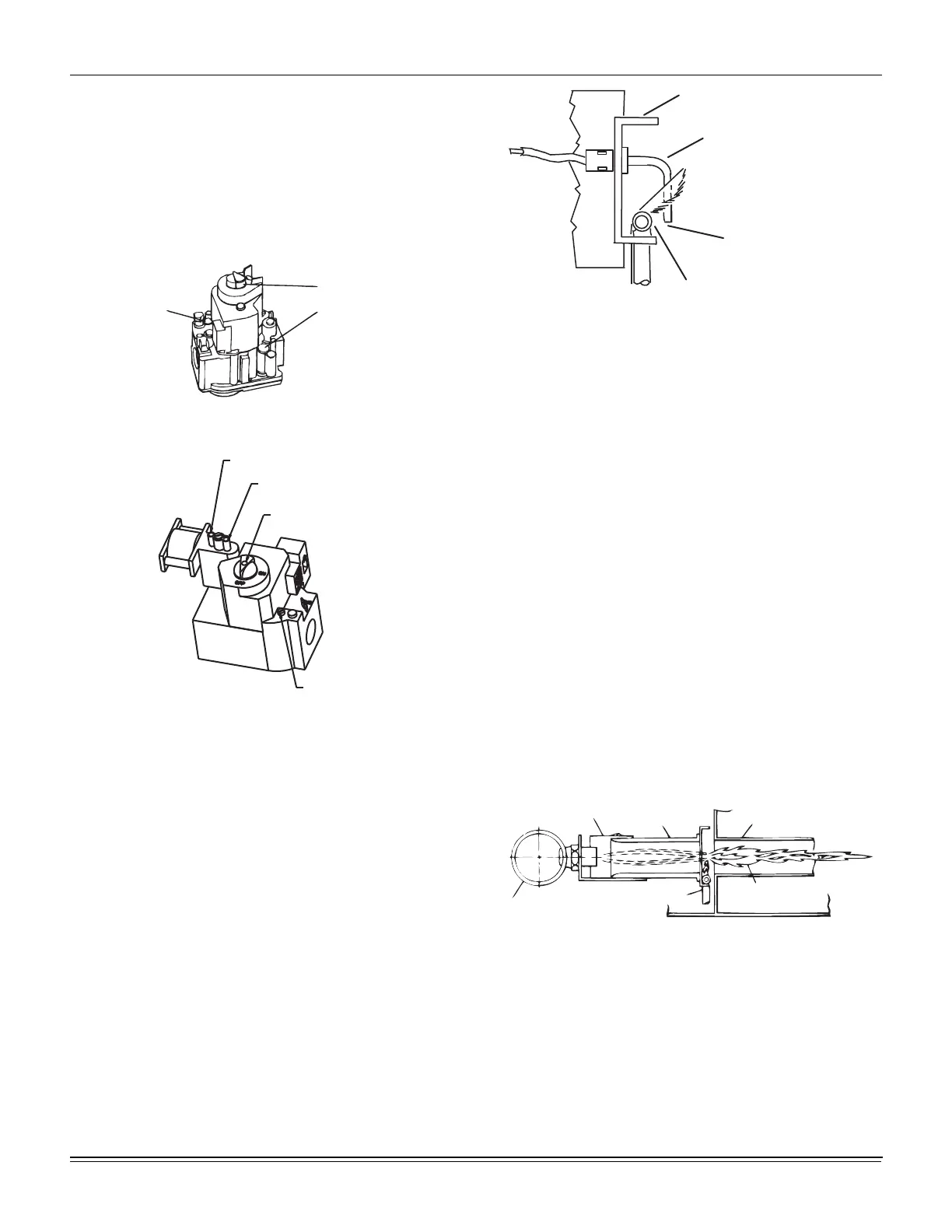
Figure 24: Typical Single Stage Gas Valves
Figure 25: Typical 2 Stage Gas Valves
Manifold Gas Pressure Adjustment
Adjustments to the high-fire and low-fire (2 stage) gas flow may
be made by turning the pressure regulator adjusting screws on
the automatic gas valve.
Adjust as follows:
1. Remove the adjustment screw cap(s) on the regulator.
2. To decrease the gas pressure, turn the adjusting screw
counterclockwise.
3. To increase the gas pressure, turn the adjusting screw
clockwise.
4. Replace adjustment screw caps.
NOTE: The factory set high-fire manifold pressure for these
furnaces is 3.50 IWG. The actual manifold pressure
depends on the local fuel heating value.
Figure 26: Proper Flame Adjustment
Pilot Checkout
The pilot flame should envelope the end of the flame sensor. To
adjust pilot flame, (1) remove pilot adjustment cover screw, (2)
increase or decrease the clearance for air to the desired level,
(3) be sure to replace cover screw after adjustment to prevent
possible gas leakage.
Put the system into operation and observe through complete
cycle to be sure all controls function properly.
Burner Instructions
To check or change burners, pilot or orifices, CLOSE MAIN
MANUAL SHUT-OFF VALVE AND SHUT OFF ALL ELECTRIC
POWER TO THE UNIT.
1. Remove the screws holding either end of the manifold to
the burner supports.
2. Open the union fitting in the gas supply line just upstream
of the unit gas valve and downstream from the main
manual shut-off valve.
3. Remove the gas piping closure panel.
4. Disconnect wiring to the gas valves and spark ignitors.
Remove the manifold-burner gas valve assembly by lifting
up and pulling back.
Figure 27: Typical Flame Appearance
Burners are now accessible for service.
Reverse the above procedure to replace the assemblies. Make
sure that burners are level and seat at the rear of the heat
exchanger.
Burner Air Shutter Adjustment
Adjust burner shutters so no yellow flame is observed in the
heat exchanger tubes.
Pilot Adj.
(Under Screw)
“ON” - “OFF” Control
“ON” - “OFF” Control
High Fire Adj.
(Under Screw)
Honeywell
VR8204M
Regulator Adj. “HI”
(Under Screw)
Regulator Adj. “LO”
(Under Screw)
“ON” - “OFF” Control
Pilot Adj.
(Under Screw)
Honeywell
VR820RQ
Burner assembly bracket
Flame sensor bulb
1/8” gap between carry-over
tube and flame sensor bulb
Carry-over tube
Gas Supply Pipe
Pilot Tube
Burner Flame
(Blue Only)
Heat Tube
Exchanger
Burner
Adjustable Shutter

 Loading...


