A19A
Issue 9811
Catalogue Section 1 © 2003 Johnson Controls Inc.
Order No. PD-A19A-E
6
A
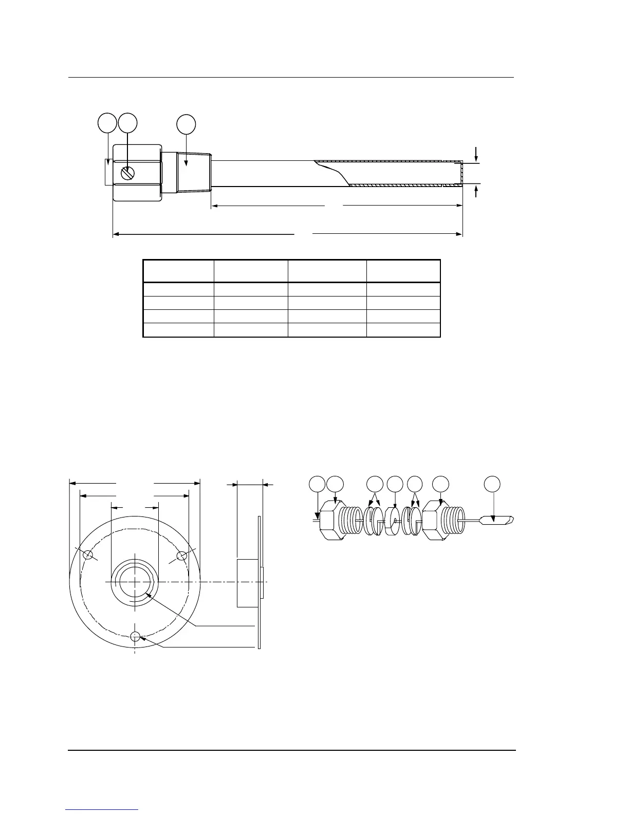
ccessories (optional)
3
2
A
B
1
C
Order no. Dimension A Dimension
B Dimension C
Internal
WEL11A601R 60 mm 118 mm 7.3 mm
WEL14A602R 125 mm 171 mm 9.8 mm
WEL14A603R 147 mm 193 mm 9.8 mm
WEL16A601R 71 mm 117 mm 9.5 mm
1. Bushing
2. Set screw
3. Adapter, 1/2"-14 NPT
Fig. 10
Bulb well (brass, copper pipe)
76
63
27
ø 5.5 (3x)
1/2"-14 NPT
11.5
Fig. 11
Duct flange to be used with closed-tank
connector FTG13A-600R.
Order number T-752-1001
3 4 3 5 621
1. Style 1b bulb support tube
2. Packing nut
3. Washer
4. Packing
5. Adapter, 1/2"-14 NPT
6 . Bulb
Fig. 12
Closed-tank connector
Order number FTG13A-600R