CK721-A Network Controller Hardware Installation
24-10025-237 Rev. –
5
ENCLOSURES
Typical mounting position for CK721-A inside the enclosure.
For more information on S300-DIN-L (large enclosure) enclosure refer to the S300-DIN-L Hardware
Installation Manual.
For more information on S300-DIN-S (small enclosure) enclosure refer to the S300-DIN-S Hardware
Installation Manual.
Mounting the CK721-A
The CK721-A module is mounted on a backplate’s DIN rail.
To mount a module, align it with the rail and snap on. To remove a module, pull the white clips
(two are located at the bottom and one on top of the module), then pull the bottom of the module
out and lift it up.
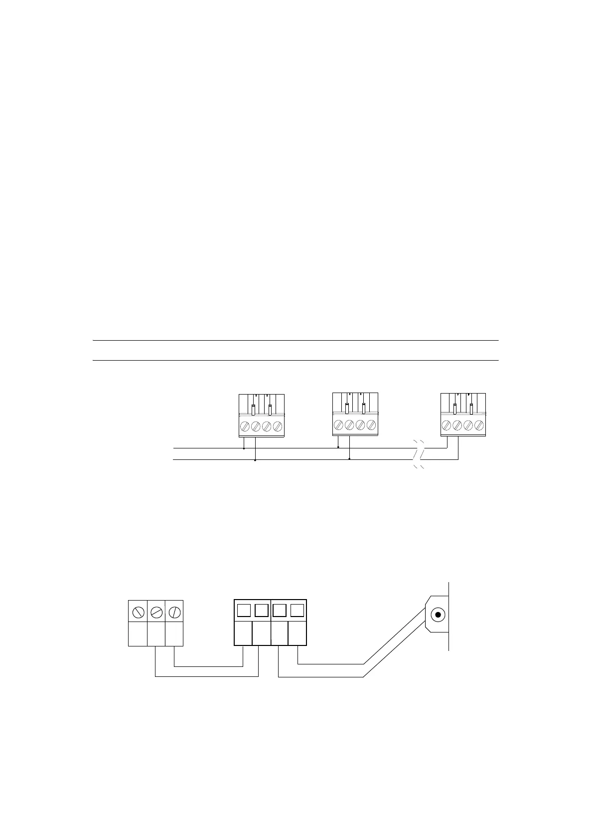
Wiring Between RS485B and the Field Devices
See the following figure for details on wiring between the RS485B and field devices.
IMPORTANT: Do not connect the DC power cable to a DIN-mounted device until all wiring is complete.
Figure 2: Wiring Between RS485B and Field Devices
Wiring Binary Inputs
See the following figure for details on binary input wiring.
Figure 3: Wiring Between Binary Inputs, Trouble Pin, and Enclosure Tamper
NO C
CK721-A
COM2
IN2
COM1
IN1
NC
S300-DIN-L
Power Supply:
TROUBLE
Enclosure
Tamper

 Loading...


