Terminal wiring guidelines,
functions, ratings, and requirements
Input and Output wiring guidelines
Table 2 provides information and guidelines about the
functions, ratings, and requirements for the controller
input and output terminals. The table also references
guidelines for determining proper wire sizes and cable
lengths.
In addition to the wiring guidelines in Table 2, observe
these guidelines when you wire controller inputs and
outputs:
• Run all low-voltage wiring and cables separate from
high-voltage wiring.
• All input and output cables, regardless of wire size or
number of wires, should consist of stranded, insulated,
and twisted copper wires.
• Shielded cable is not required for input or output
cables.
• Shielded cable is recommended for input and output
cables that are exposed to high electromagnetic or
radio frequency noise.
• Inputs/outputs with cables less than 30 m (100 ft)
typically do not require an offset in the software setup.
Cable runs over 30 m (100 ft) may require an offset in
the input/output software setup.
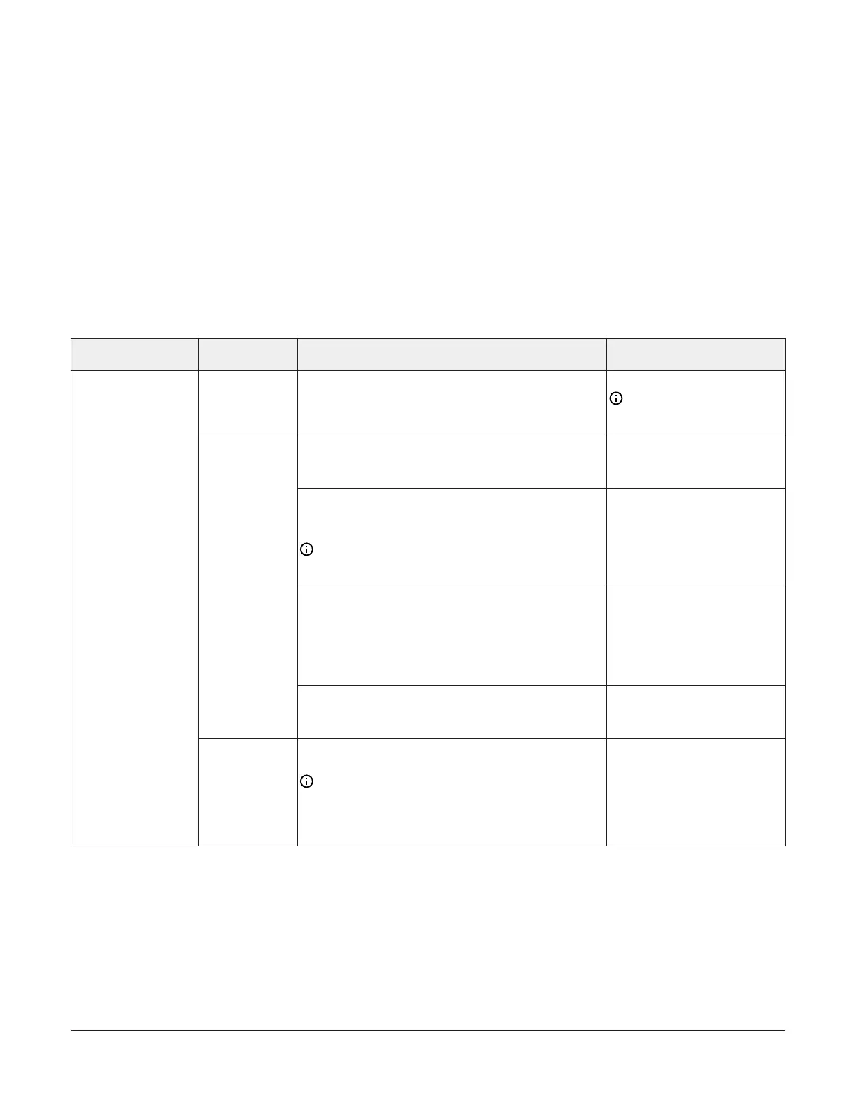
I/O Terminal blocks, ratings, and
requirements
Table 2: Terminal blocks, functions, ratings, requirements, and cables
Terminal block label Terminal label Function, ratings, requirements
Determine wire size and
maximum cable length
+15 V
15 VDC Power Source for active (3-wire) input devices
connected to the Universal INn terminals.
Provides 100 mA total current
Same as (Universal) INn
Note: Use 3-wire cable for
devices that source power
from the +15V terminal.
Analog Input - Voltage Mode (0–10 VDC)
10 VDC maximum input voltage
Internal 75k ohms pull-down
See Guideline A in Table 3.
Analog Input - Current Mode (4–20 mA)
Internal 100 ohms load impedance. See Setting the Input
Jumpers.
Note: A current loop fail-safe jumper must be in
the Enable position to maintain a closed 4 to 20 mA
current loop. See UI current loop jumpers.
See Guideline B in Table 3.
Analog Input - Resistive Mode (60–600k ohms)
Internal 12 V. 15k ohms pull-up
Qualified Sensors: 0–2k ohms potentiometer, RTD (1k
Nickel [ Johnson Controls
®
sensor], 1k Platinum, and
A99B Silicon Temperature Sensor) Negative Temperature
Coefficient (NTC) Sensor
See Guideline A in Table 3.
INn
Binary Input - Dry Contact Maintained Mode
1 second minimum pulse width
Internal 12 V. 15k ohms pull-up
See Guideline A in Table 3.
UNIVERSAL
(Inputs)
ICOMn
Universal Input Common for all Universal Input
terminals
Note: All Universal ICOMn terminals share a
common, which is isolated from all other commons,
except the SA bus common. One common screw
terminal point is provided for every two input screw
terminal points.
Same as (Universal) INn
FAC3611 Advanced Application Controller Installation Guide6