Installation
Observe the following guidelines when installing a field
controller:
• To minimize vibration and shock damage, transport the
controller in the original container.
• Verify that all parts shipped with the controller.
• Do not drop the controller or subject it to physical
shock.
Parts included
• One field Controller. (Power and SA bus terminal blocks
are removable)
• One installation instructions sheet.
Materials and special tools needed
• Three fasteners appropriate for the mounting surface
(M4 screws or #8 screws)
• One 23 cm (9.125 in.) or longer piece of 35 mm DIN rail
and appropriate hardware for DIN rail mount (only)
• Small straight-blade screwdriver for securing wires in
the terminal blocks
FAC3611 physical features
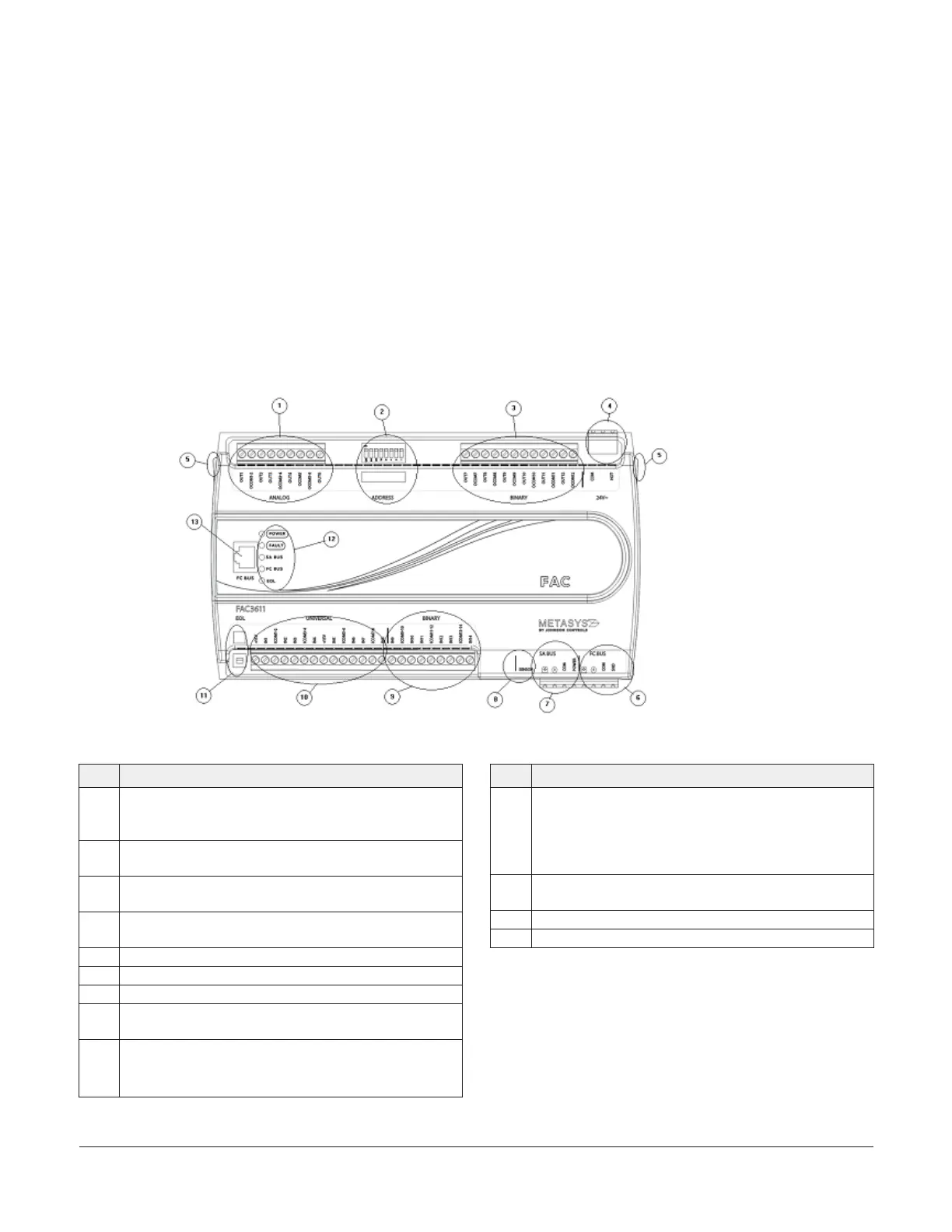
Figure 1: FAC3611 Physical Features
Table 1: Physical features
Physical feature: description and references
1
Analog Output (AO) Terminal Block: Can be defined as
Voltage Analog Output (0–10 VDC) or Current Analog
Output (4–20 mA) (see Table 2)
2
Device Address DIP Switch Block (see Setting the Device
Addresses)
3
Binary Outputs (BO) Terminal Block: 24 VAC Triac (see
Table 2)
4
24 VAC, Class 2/SELV Supply Power Terminal Block (see
Supply power terminal block)
5 Cover Lift Tab (One of Two)
6 FC Bus Terminal Block (see FC bus terminal block )
7 SA Bus Terminal Block (see SA bus terminal block)
8
Sensor Port: (SA Bus) RJ-12 6-Pin Modular Jack (see SA Bus
port )
9
Binary Input (BI) Terminal Block: Dry Contact Maintained
or Pulse Counter/Accumulator Mode (see Terminal wiring
guidelines, functions, ratings, and requirements
Table 1: Physical features
Physical feature: description and references
10
Universal Inputs (UI) Terminal Block: Can be defined as
Voltage Analog Input (0–10 VDC), Current Analog Input
(4–20 mA), Resistive Analog Inputs (0–600k ohms), or
Dry Contact Binary Input (see Input and Output wiring
guidelines)
11
End-of-Line (EOL) Switch (see Setting the End-of-Line
(EOL) switch)
12 LED Status Indicators (see Table )
13 FC Bus Port (RJ-12 6-pin Modular Jack)
Mounting
Observe the following guidelines when mounting a field
controller:
• Ensure the mounting surface can support the
controller, DIN rail, and any user-supplied enclosure.
• Mount the controller horizontally on 35 mm DIN rail
whenever possible.
FAC3611 Advanced Application Controller Installation Guide2