130 4280 010 E
Terminal Box Replacement
CAUTION: Equipment damage hazard. Ensure that the replacement terminal box matches the
existing one in every respect.
CAUTION: Equipment damage hazard. Label all wires prior to disconnection when servicing valves.
Wiring errors can cause improper and dangerous operation. Verify proper operation after servicing.
Follow the procedure below to replace the terminal box.
• Close the upstream shutoff cock, disconnect power to the actuator.
• Remove the terminal box cover by loosen the four cover screws.
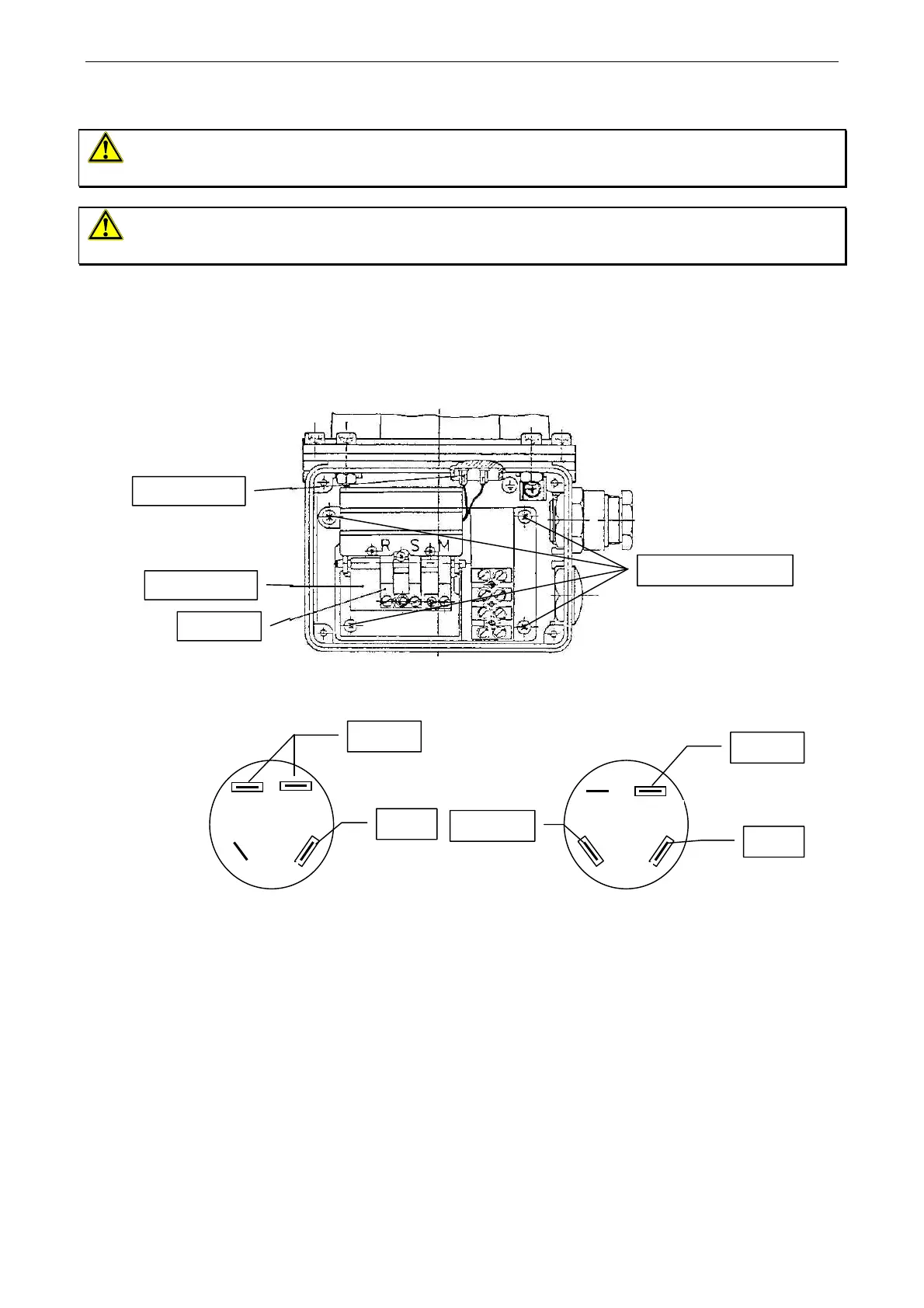
• Disconnect field wiring. Disconnect the flat plugs from the plug connector. See Figure 5.
• Loosen the four terminal box mounting screws. Lift the key lever and pull out the terminal box.
• Connect the flat plugs of the new terminal box to the plug connector in accordance with Figure 6. Please note
that the Th and 2 pins are towards the front and the 1 and N pins are towards the back of the terminal box.
Flat Plu
s
Mounting Screws
Ke
Lever
Lever
Figure 5: Terminal box
black
brown
blue
blue
brown
N
2
1
Th
2
1 N
Th
On-Off Version On-Low-Off Version
Ignition On-Low-Off Version
Figure 6: Flat plug connector
• Lift the key lever and insert the replacement terminal box into the housing. Ensure that the back of the
key lever is inserted into the opening in the back of the housing.
• Attach the terminal box to the housing using the four mounting screws. Tighten the screws in the
numbered order shown in to ensure that the terminal box is flat.
• Connect field wiring to the terminal box.
• If necessary, make switch adjustments. Refer to the Adjustments section for details.
• Reattach the terminal box cover by tightening the four cover screws.
• Apply power to the actuator and open the upstream shutoff cock.
• Observe at least three complete operating cycles to ensure that all components are functioning correctly.
Johnson Controls SA/NV - Leuvensesteenweg 248D - B-1800 Vilvoorde - +32(2) 709 40 00 - www.johnsoncontrols.be