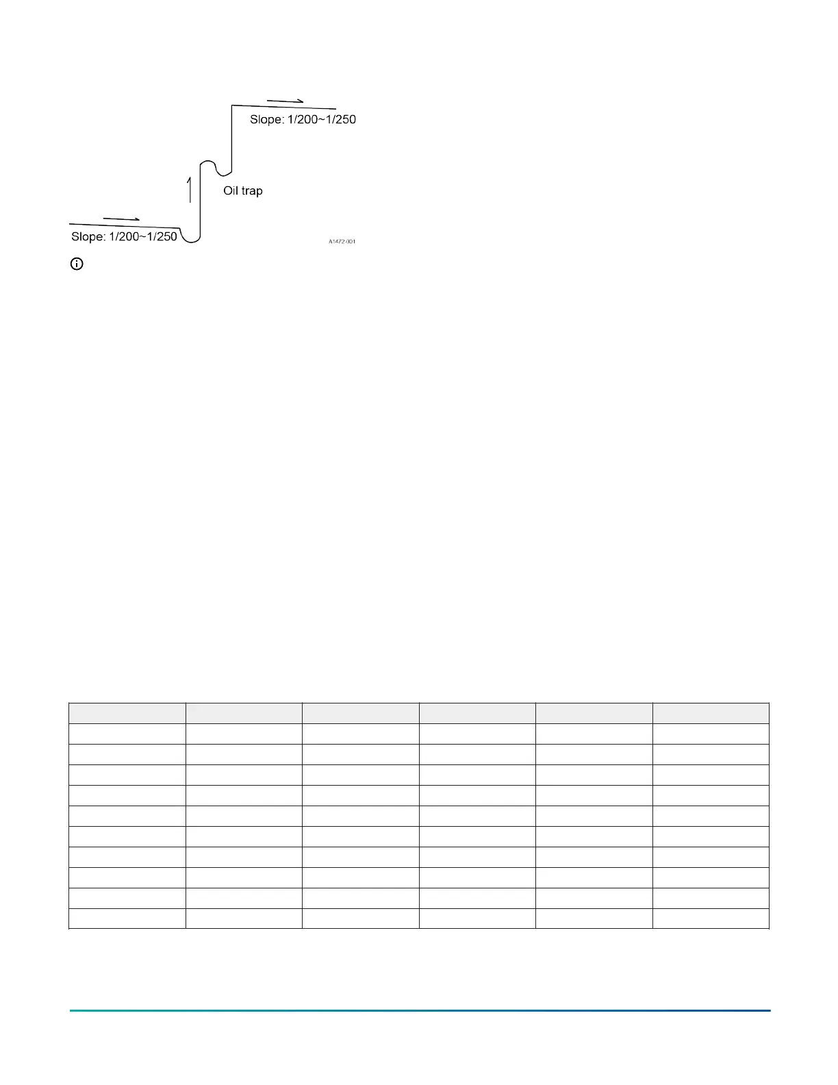
Figure 36: Oil trap
Note:
1. To avoid storing too much oil in the oil trap
and to ensure better cooling and heating
performance, the oil trap must be as short and
as straight as possible.
2. The horizontal piping must slope toward the
trap or outdoor section at a slope of 1/8 in/ft
for proper oil return.
Control mode
Control function
1. Cooling anti-freeze protection: The outdoor
pressure sensors monitor evaporator pressure and
saturated temperature. This feature prevents the
indoor unit evaporator temperature from becoming
too low. If the indoor coil temperature is too low, the
compressor automatically engages protection mode.
2. Overload protection: To prevent system overload
caused by excessive pressure, the control
implements real-time detection when the outdoor
coil temperature is too high during cooling mode
or the indoor coil temperature is too high during
heating mode.
3. Compressor discharge temperature protection:
To prevent damage due to a high compressor
discharge temperature, the control monitors the
discharge gas temperature and provides automatic
protection if the temperature is too high.
4. Oil-return control: When the compressor runs at
low frequencies for a long time, the control initiates
an oil-return sequence to ensure oil is returned to
the compressor.
5. Operation mode: Air conditioning mode is
the operation mode set by users through the
thermostat. Two modes are available: cooling and
heating.
6. Four-way valve control: The four-way valve of
the outdoor unit is de-energized in cooling and
defrosting, and energized in heating. During
heating, the four-way valve is de-energized for a
period of time after the compressor stops.
7. Start-up protection: To prevent frequent
compressor starts where the system pressure has
not equalized, the control invokes a delay of 3 min
between cycles to prevent short cycles.
8. Pressure protection: When the pressure increases
to a preset value, the pressure switch automatically
changes to protection mode. The compressor stops
and reports the protection fault code.
Sensor parameter
These are the parameters for the outdoor compressor discharge sensor:
(R0=187.25K±6.3%, R100=3.77K±2.5K, B0/100=3979K±1%)
Table 8: Outdoor compressor discharge temperature sensor
T [ ℃ ] Rmin [ KΩ ] Rnom [ KΩ ] Rmax [ KΩ ] Dev(MIN)% Dev(MAX)%
-30 908.2603 985.5274 1065.1210 -7.84 7.47
-15 384.2888 413.3808 442.9105 -7.04 6.67
0 175.4533 187.2500 199.0468 -6.30 5.93
15 85.4114 90.4842 95.5398 -5.61 5.29
30 44.1034 46.4046 48.6960 -4.96 4.71
45 23.9697 25.0632 26.1488 -4.36 4.15
60 13.6400 14.1799 14.7154 -3.81 3.64
75 8.0951 8.3705 8.6440 -3.29 3.16
90 4.9853 5.1292 5.2726 -2.81 2.72
105 3.1632 3.2491 3.3353 -2.64 2.58
These are the parameters for the suction, ambient, coil, and discharge sensors: (R0=15K±2%, B0/100=3450K±2%)
Installation Manual: HMH7 Series - 17 SEER Horizontal Discharge Modulating Heat Pump 31
Johnson Controls Ducted Systems