Johnson Controls, Inc. SLC Wiring Manual — P/N 51870:G 04/23/2009 11
SLC Overview Introduction
1.4 SLC Overview
Communication between the control panel and intelligent addressable monitor and control devices
takes place through a Signaling Line Circuit (SLC), which can be wired to meet the requirements of
NFPA Style 4, Style 6, or Style 7.
At least one secondary surge protector must be used with each SLC wiring pair whenever SLC
wiring runs outside the building. For detailed information refer to Appendix B, “SLC Surge
Suppression”, on page 58.
1.5 Polling Protocols
FlashScan®
is a patented system (US Patent Number 5,539,389) that greatly enhances the speed of
communication between analog intelligent devices. Communication is in a grouped fashion. If one
of the devices within the group has new information, the panel CPU stops the group poll and
concentrates on single points. Not all panels are FlashScan® capable; see “Protocol Use” below.
CLIP (Classic Loop Interface Protocol) polls devices in sequential order. Many but not all
FlashScan-capable devices can be set to run in CLIP mode; see installation sheet shipped with the
device.
Protocol Use: LCM-320/LEM-320 loops on IFC2-640, IFC-640/E and IFC-3030/IFC2-3030, and
SLC loops on IFC-320 can run in FlashScan mode or CLIP mode. IFC-200, IFC-300/IFC-400,
IFC-1010 and IFC-2020 run in CLIP mode only.
Many FlashScan devices can be programmed to run in either CLIP or FlashScan mode. Use one of
the following three options with SLC loops:
1. Program all modules and detectors on an SLC as FlashScan.
2. Program all modules and detectors on an SLC as CLIP.
3. Program all detectors as CLIP and all modules as FlashScan on an SLC.
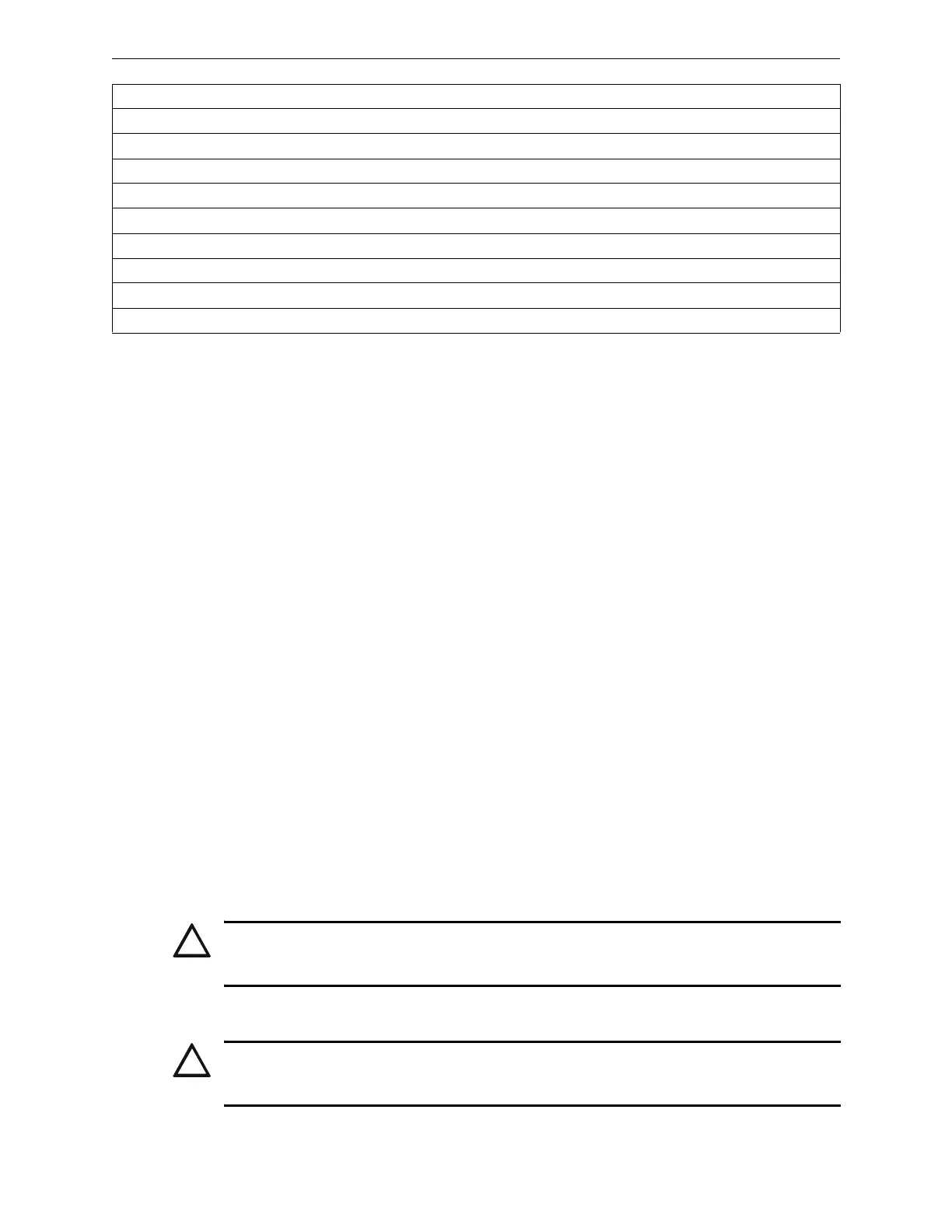
2951J, 2951TJ and 2951TMJ (Acclimate™) Photoelectric Detectors Installation Document I56-1930
5351J Thermal Detector Installation Document I56-1363
5351RJ Rate of Rise Sensor Installation Document I56-1634
5951J, 5951RJ, and 5951HJ Thermal Detectors Installation Document I56-1931
M500FPJ Firephone Control Module I56-2550
M302MJ Zone Interface Module Installation Document I56-1212
FTX-P1J HARSH™ (CLIP mode) Installation Document I56-1485
M500XJ Isolator Module Installation Document I56-1384
JBG-12LX Addressable Pull Station Installation Document 51242
Note: Refer to the Device Compatibility Document for compatible conventional devices.
Table 1.1 Reference Documentation (3 of 3)
!
CAUTION:
Do not program more than 99 addresses on a CLIP-mode SLC loop, because this will slow the
system down and compromise the response time of the panel to display off-normal events.
!
CAUTION:
Do not program modules as CLIP and detectors as FlashScan on the same SLC. This combination
does not work.

 Loading...


