62 Johnson Controls, Inc. SLC Wiring Manual — P/N 51870:G 04/23/2009
SLC Surge Suppression Installation
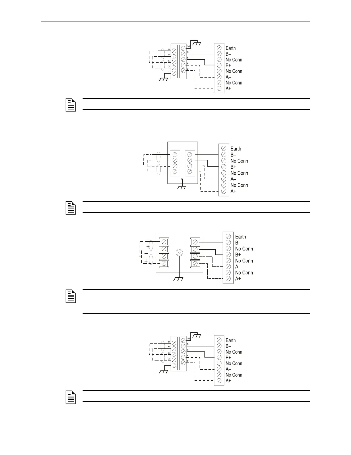
SLCP-30 Connections
B.2.4 IFC-640/E, IFC-3030/IFC2-3030
DTK-2LVLP-F Connections
PLP-42N Connections
SLCP-30 Connections
IN OUT
SLCP-30
+
+
–
–
SLC Terminal Block
SLC Loop
SLC-slcp3.cdr
Optional Four-wire
Return Loop
Style 6 (Class A)
NOTE: Do not connect shield (if present) to surge protector or fire panel.
IN OUT
2LVLP-F
–
–
+
+
SLC-lvlp3.cdr
SLC Terminal Block
SLC Loop
Optional Four-wire
Return Loop
Style 6 (Class A)
NOTE: Do not connect shield (if present) to surge protector or fire panel.
INPUT
OUTPUT
PLP-42N
L1 L2 L3 L4
L1 L2 L3 L4
GRND
SLC-plpn3.cdr
SLC Terminal Block
SLC Loop
Optional Four-wire
Return Loop
Style 6 (Class A)
NOTE: Use 12 AWG (3.31 mm
2
) to 18 AWG (0.82 mm
2
) wire with crimp-on connectors to
connect the unit’s ground terminal to equipment ground. Wire length must be minimized to
provide best protection. Do not connect shield (if present) to surge protector or fire panel.
IN OUT
SLCP-30
+
+
–
–
SLC Terminal Block
SLC Loop
SLC-slcp3.cdr
Optional Four-wire
Return Loop
Style 6 (Class A)
NOTE: Do not connect shield (if present) to surge protector or fire panel.

 Loading...


