48 Johnson Controls, Inc. SLC Wiring Manual — P/N 51870:G 04/23/2009
Section 9: Intelligent Detector Bases
9.1 Description
The B501J and B210LPJ Detector Bases, the B224RB plug-in relay detector base, and the
B501BH sounder base provide the connection between the SLC and a variety of intelligent
detectors. Use the B501B-FTXJ Detector Base with all HARSH™ detectors.
For more information refer to the Installation Instructions documents provided with these devices.
Setting the Detector Address
Each intelligent detector head is factory preset with an address of “00.” To set an SLC address refer
to “Setting an SLC Address for a Module” on page 35.
9.2 Wiring a Detector Base
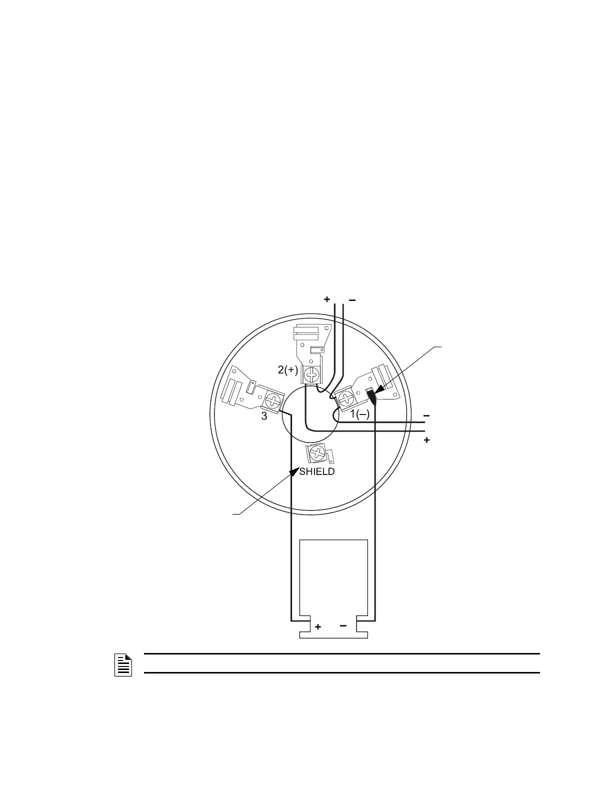
Figure 9.1 shows typical wiring of the B210LPJ or B501J detector base connected to an SLC. An
optional RA400Z Remote LED Annunciator is shown connected to the base.
Figure 9.1 Wiring of the B501J Detector Base
To next device
on SLC
SLC
SLC-B501wire.wmf
RA400Z
Remote LED
Annunciator
(Optional)
B501 only: For connection of
cable shield
Use a female disconnect
to wire the RA400Z (–) to
Terminal 1 (–).
NOTE: The B210LPJ base wiring is identical to the B501J, except there is no shield terminal.

 Loading...


