JOHNSON CONTROLS
29
SECTION 3 - PRE START-UP CHECKLIST
FORM 145.05-SU7
ISSUE DATE: 10/31/2019
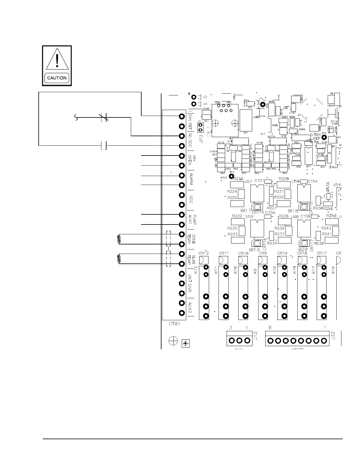
FIGURE 2 - FIELD CONTROL WIRING - INPUTS
CTB1 FIELD CONTROL WIRING (INPUTS)
A 24 VAC switch voltage must be sourced
from the unit. Use of another power
source external of the unit may cause
equipment damage.
PUMP START
ALARM
VAV HEAT
See Note 7
Zone Temp. Sensor
FlexSys Slab Temp. Sensor
Caution: 24 VAC switch voltage must
be sourced from the unit. Use of
another power source external of the
unit may cause equipment damage
.
Remote Shutdown (SD)
Open = Shutdown
Closed = Run
Closed = Occupied
Open = Unoccupied
261
See Note 6
See Note 8
262
LD13325A
Wiring Notes:
1. Wiring shown indicates typical wiring. Refer to the IOM for more detailed wiring methods and options.
2. All wiring is Class 2, low voltage.
3. Maximum power available from the 24VAC terminal is 40 VA.
4. Use shielded wire where shown.
5. Relay contacts suitable for pilot duty to 1A from 24 VAC to 120VAC
6. Wire 261 must be removed from the SD terminal and connected to one side of a eld installed, normally closed contact. The other side of
the normally closed contact is connected to the SD terminal.
7. Dry contact closes when VAV boxes should open.
8. When the rocker switch is placed in the ON position it provides an Occupied and Shutdown command for the unit to run.
9. In the AUTO position only the Shutdown terminal is provided 24vac to make the unit run. An occupancy command must be provided by
hardwiring to OCC, communicating, or through the unit timeclock.

 Loading...


