M Motor Actuators—M100C Series of Motor Actuators 11
20
21
42
41
40
39
38
37
36
35
34
33
32
31
30
29
28
27
C500AAC-1
Power
Supply
CW
CCW
COM
BUS
T
2
T
1
CA-1
CW
CCW
COM
BUS
T
2
T
1
CA-4
CW
CCW
COM
BUS
T
2
T
1
CA-2
Power
Supply
Power
Supply
TE-1
TE-2
TE-3
TE-4
AFS-1
AFS-2
TC-1
HT-1
HT-2
Power
Supply
Power
Supply
Power
Supply
TZ-4
TZ-5
TZ-6
TZ-3
TZ-2
45 678
OFF
ADDRESS 17
TZ-1
*
**
**
**
*Shield is connected to Common of the controller.
**Loose ends of the shield are to be taped off as
required. Do not connect to ground.
Slave
Master
45
678
OFF
ADDRESS 17
Slave
45 678
OFF
ADDRESS 17
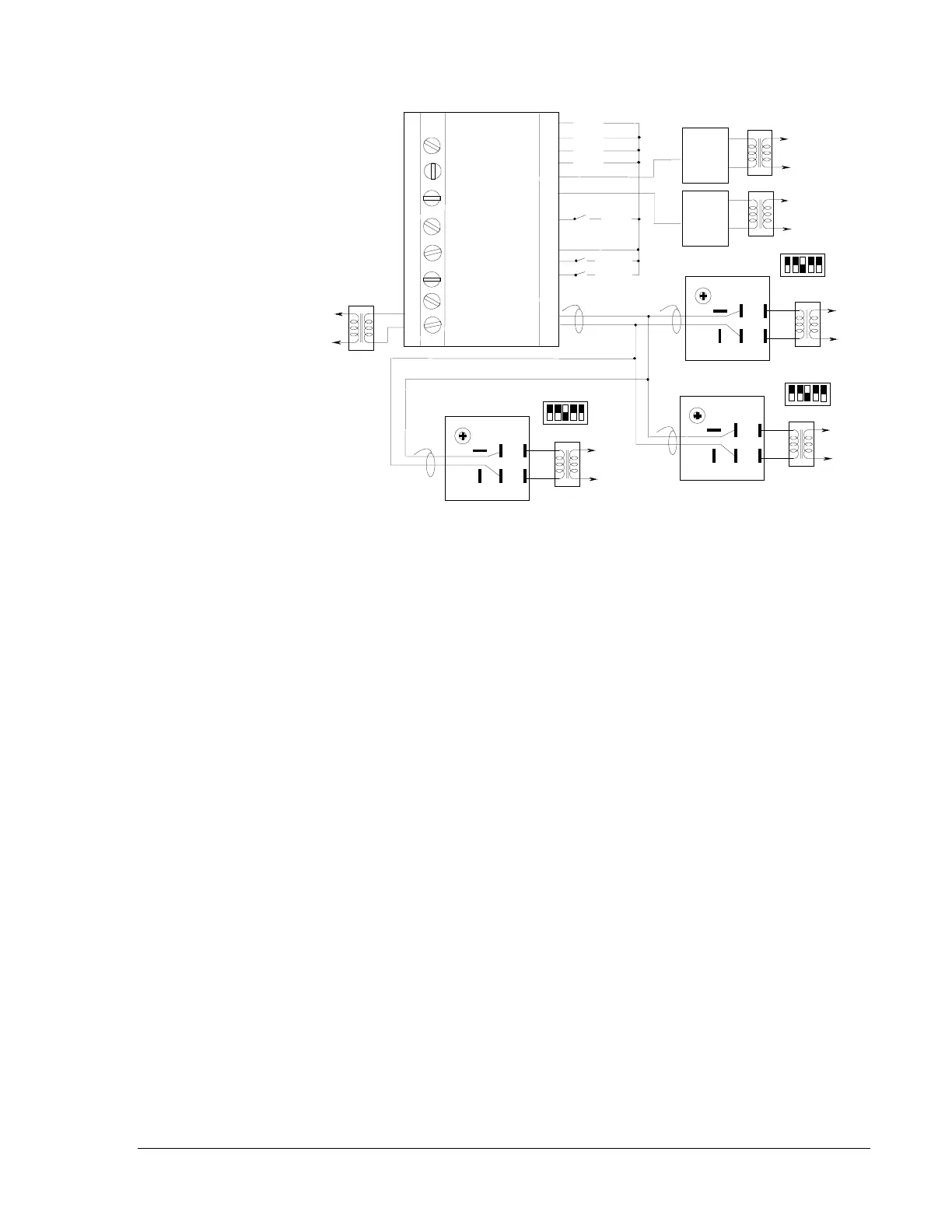
Figure 11: Typical Parallel Wiring Diagram All Master Actuators
Figure 11 shows a typical wiring diagram for a parallel system with one
motor actuator set as master and the others as slaves. Each motor actuator
has the same address.
To wire the motor actuator:
1. Loosen the two screws securing the top cover and remove the top
cover for access to the wiring terminals.
2. Use a hammer and punch to drive out one of the access hole covers.
3. Install the conduit connector to the motor actuator and secure using the
conduit nut provided with the connector.
4. Connect the controller to the terminals located in the wiring
compartment as shown in Figures 9 and 10.
5. Connect 24 VAC to terminals T1 and T2.
Note: To avoid potential miswiring and electrical problems, the use of
separate transformers for each M100 is required.
Note: For further information on any of the controllers illustrated,
reference the applicable controller literature.