10 M Motor Actuators—M100C Series of Motor Actuators
24 VAC
Power
Supply
CW
CCW
COM
BUS
T
2
T
1
M100C
Level 1 Bus or
Zone Bus
from Controller
Tape off the shield
end at the motor
actuator. Connect
the shield only at
the controller.
M100C06
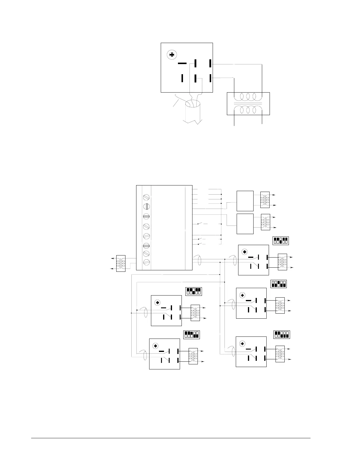
Figure 9: Typical Single Unit Wiring Diagram
Connect the shield only at the controller. Do not connect shield to any
other point.
20
21
42
41
40
39
38
37
36
35
34
33
32
31
30
29
28
27
C500AAC-1
Power
Supply
CW
CCW
COM
BUS
T
2
T
1
CA-3
CW
CCW
COM
BUS
T
2
T
1
CA-1
CW
CCW
COM
BUS
T
2
T
1
HMA-2
CW
CCW
COM
BUS
T
2
T
1
CA-4
CW
CCW
COM
BUS
T
2
T
1
CA-2
Power
Supply
Power
Supply
TE-1
TE-2
TE-3
TE-4
AFS-1
AFS-2
TC-1
HT-1
HT-2
Power
Supply
Power
Supply
Power
Supply
Power
Supply
Power
Supply
TZ-9
TZ-6
TZ-4
TZ-5
TZ-7
TZ-3
TZ-2
12
3
45
OFF
ADDRESS 23
12
345
OFF
ADDRESS 24
12 345
OFF
ADDRESS 20
12 34
5
OFF
ADDRESS 14
45 678
OFF
ADDRESS 17
TZ-1
*
**
**
**
**
**
*Shield is connected to Common of the controller.
**Loose ends of the shield are to be taped off as
required. Do not connect to ground.
Figure 10: Typical Parallel Wiring Diagram All Master Actuators
Figure 10 shows a typical wiring diagram for a parallel system with all
motor actuators set as master. Each motor actuator has a separate address.