Parts included
• One CGM controller with removable terminal
blocks (Input/Output, Power, FC, and SA bus are
removable)
• One installation instructions sheet
Materials and special tools needed
• Three fasteners appropriate for the mounting
surface (M4 screws or #8 screws)
• One 20 cm (8 in.) or longer piece of 35 mm DIN
rail and appropriate hardware for DIN rail mount
(only)
• Small straight-blade screwdriver for securing
wires in the terminal blocks
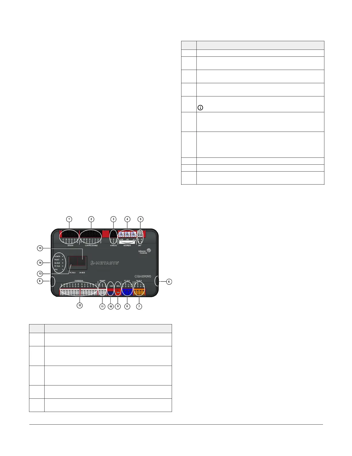
CGM09090 physical features
The following figure displays the physical features
of the CGM controllers, and the accompanying table
provides a description of the physical features and a
reference to further information where required.
Figure 1: CGM09090 Physical Features
Table 1: CGM09090 physical features
Physical Feature: Description and References
1
Binary Outputs (BO) Terminal Block: Black terminals; 24
VAC Triac (see Table 5)
2
Configurable Outputs (CO) Terminal Block: Black
terminals; can be defined as Voltage Analog Output (0-10
VDC) or Binary Output (24 VAC Triac) (see Table 5)
3
Analog Output (AO) Terminal Block: Black terminals;
can be defined as Voltage Analog Output (0-10 VDC) or
Current Analog Output (4-20 mA) (see Table 5)
4
Device Address Rotary Switch Block: Decimal Addressing
(see Setting the device address)
5
Supply Power Terminal Block: Gray terminals; 24 VAC,
Class 2 (see Supply power terminal block)
Table 1: CGM09090 physical features
Physical Feature: Description and References
6 Cover Lift Tab (see Removing the controller cover)
7
Sensor Actuator (SA) Bus Terminal Block: Orange terminal
(see SA bus terminal block)
8
Field Controller (FC) Bus Terminal Block: Blue terminal
(see FC bus terminal block (or N2 protocol as required))
9
End-of-Line (EOL) Switch (see Setting the End-of-Line
(EOL) switch)
10
Universal Serial Bus (USB) 2.0 host type A Port
Note: The USB feature is not currently supported.
11
Binary Input (BI) Terminal Block: White terminals; dry
Contact Maintained or Pulse Counter/Accumulator Mode
(see Table 5)
12
Universal Inputs (UI) Terminal Block: White terminals; can
be defined as Voltage Analog Input (0-10 VDC), Current
Analog Input (4-20 mA), Resistive Analog Inputs (0-600k
ohm), or Dry Contact Binary Input (see Table 5)
13 FC Bus Port RJ-12 6-pin Modular Jack (see FC bus port)
14 LED Status Indicators (see Table 11)
15
Sensor (SA Bus) Port: RJ-12 6-Pin Modular Jack (see SA Bus
port)
Mounting
Observe the following guidelines when mounting a
CGM controller:
• Ensure the mounting surface can support the
controller, DIN rail, and any user-supplied
enclosure.
• Mount the controller horizontally on 35 mm DIN
rail whenever possible.
• Mount the controller in the proper mounting
position.
• Mount the controller on a hard, even surface
whenever possible in wall-mount applications.
• Use shims or washers to mount the controller
securely and evenly on the mounting surface.
• Mount the controller in an area free of corrosive
vapors and observe the Ambient Conditions
requirements in Table 14.
• Provide for sufficient space around the controller
for cable and wire connections for easy cover
removal and good ventilation through the
controller (50 mm [2 in.] minimum on the top,
bottom, and front of the controller).
• Do not mount the controller on surfaces prone to
vibration, such as duct work.
M4-CGM General Purpose Application Controllers Installation Guide2