Input and Output wiring guidelines
Table 5 provides information and guidelines about
the functions, ratings, and requirements for the
controller input and output terminals, and Table 6
also references guidelines for determining proper
wire sizes and cable lengths.
In addition to the wiring guidelines in Table 5,
observe these guidelines when wiring controller
inputs and outputs:
• Run all low-voltage wiring and cables separate
from high-voltage wiring.
• All input and output cables, regardless of wire size
or number of wires, should consist of stranded,
insulated, and twisted copper wires.
• Shielded cable is not required for input or output
cables.
• Shielded cable is recommended for input
and output cables that are exposed to high
electromagnetic or radio frequency noise.
• Inputs/outputs with cables less than 30 m (100 ft)
typically do not require an offset in the software
setup. Cable runs over 30 m (100 ft) may require
an offset in the input/output software setup.
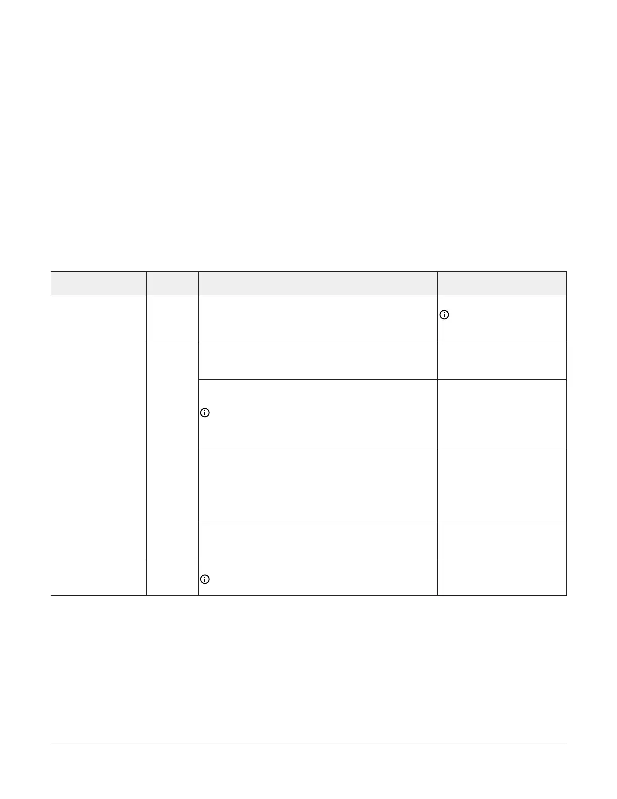
I/O terminal blocks, ratings and requirements
Table 5: I/O terminal blocks, functions, ratings, requirements, and cables
Terminal Block label
Terminal
label
Function, ratings, requirements
Determine wire size and
maximum cable length
+15 V
15 VDC Power Source for active (3-wire) input devices
connected to the Universal INn terminals.
Provides 100 mA total current
Same as (Universal) INn
Note: Use 3-wire cable for
devices that source power
from the +15V terminal.
Analog Input - Voltage Mode (0–10 VDC)
10 VDC maximum input voltage
Internal 10k ohm Pull-down
See Guideline A in Table 6
Analog Input - Current Mode (4–20 mA)
Internal 100 ohm load impedance
Note: Current loop jumpers are fail-safe to maintain a
closed 4 to 20 mA current loop, even when the power to
the controller is interrupted or off. See UI current loop
jumpers.
See Guideline B in Table 6.
Analog Input - Resistive Mode (0–600k ohm)
Internal 12 V. 15k ohm pull up
Qualified Sensors: 0-2k ohm potentiometer, RTD (1k Nickel
[Johnson Controls
®
sensor], 1k Platinum, and A99B Silicon
Temperature Sensor) Negative Temperature Coefficient (NTC)
Sensor
See Guideline A in Table 6.
INn
Binary Input - Dry Contact Maintained Mode
1 second minimum pulse width
Internal 12 V. 15k ohm pull up
See Guideline A in Table 6.
UNIVERSAL
(Inputs)
ICOMn
Universal Input Common for all Universal Input terminals
Note: All Universal ICOMn terminals share a common,
which is isolated from all other commons.
Same as (Universal) INn
M4-CGM General Purpose Application Controllers Installation Guide 7