• Do not mount the controller in areas where
electromagnetic emissions from other
devices or wiring can interfere with controller
communication.
On panel or enclosure mount applications, observe
the following additional guidelines :
• Mount the controller so that the enclosure walls
do not obstruct cover removal or ventilation
through the controller.
• Mount the controller so that the power
transformer and other devices do not radiate
excessive heat to the controller.
• Do not install the controller in an airtight
enclosure.
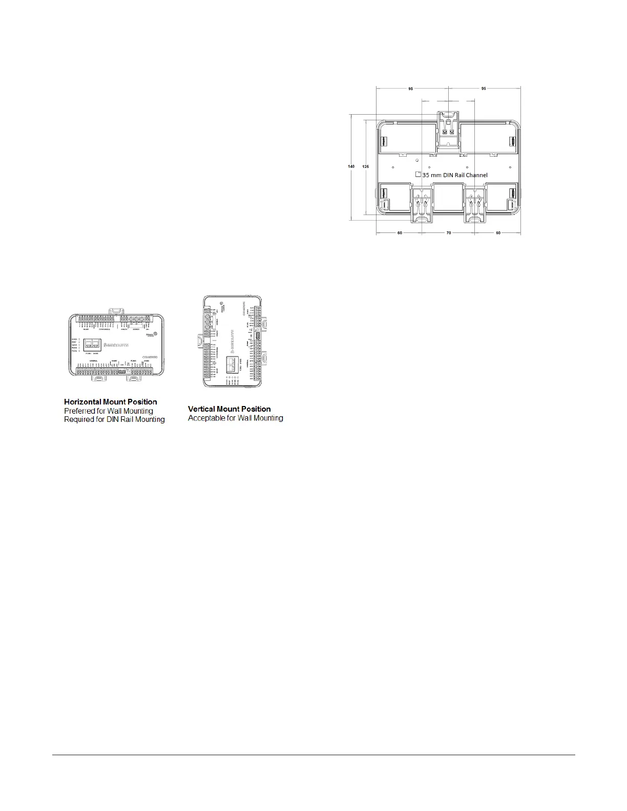
Figure 2: Controller mounting position
Mounting features and dimensions
See the Figure 3 for mounting dimensions in
millimeters. Figure 3 also illustrates the DIN rail
channel and the mounting clips in an extended
position.
Figure 3: Back of controller
DIN rail mount applications
To mount a CGM controller horizontally on a 35
mm DIN rail (recommended method), complete the
following steps:
1. Securely mount a 20 cm (8 in.) or longer section
of 35 mm DIN rail horizontal and centered in the
desired space so that the controller mounts in
the horizontal position.
2. Pull the two bottom mounting clips outward
from the controller to the extended position
(Figure 3).
3. Hang the controller on the DIN rail by the hooks
at the top of the (DIN rail) channel on the back
of the controller (Figure 3), and position the
controller snugly against the DIN rail.
4. Push the bottom mounting clips inward (up) to
secure the controller on the DIN rail.
To remove the controller from the DIN rail, pull the
bottom mounting clips out to the extended position
and carefully lift the controller off the DIN rail.
Wall mount applications
To mount a CGM controller directly on a wall or
other flat vertical surface, complete the following
steps:
1. Pull the two bottom mounting clips outward
and ensure they are locked in the extended
position as shown in Figure 3.
M4-CGM General Purpose Application Controllers Installation Guide 3