Troubleshooting equipment
controllers
Table 9 provides LED status indicator information for troubleshooting the CVM03050 controller. General
troubleshooting provides some additional troubleshooting information for possible problems.
Note: If you experience short circuits in the 24
VAC power supply causing protective devices
such as breakers or fuses to trip, make sure
that the power connections on the CVM are
not reversed. The most common cause of this
problem is when the 24 VAC power supply
on the CVM is reversed but not reversed on a
connected secondary device.
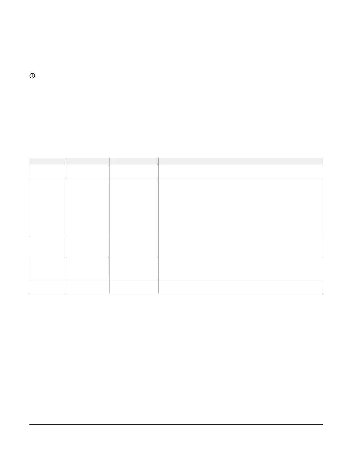
LED status and states
Table 9: Status LEDs and description of LED states
LED label LED color Normal state Descriptions of LED states
POWER Green On Steady
Off Steady = No power
On Steady = Power is supplied by primary voltage
FAULT Red Off Steady
2 blinks followed by long pause = Controller powered on in default state.
For more information about this default state, see Input and output wiring
validation.
Blink - 2 Hz = Download or startup in progress, not ready for normal
operation, SA Bus devices offline (such as netsensors)
Rapid blink = SA Bus communications issue
Off Steady = No faults
On Steady = Device fault or no application loaded
FC BUS Green Blink - 2 Hz
Blink - 2 Hz = Data transmission (normal communication)
Off Steady = No data transmission (auto baud in progress)
On Steady = communication lost, waiting to join communication ring
SA BUS Green Blink - 2 Hz
Blink - 2 Hz = Data transmission (normal communication)
Off Steady = No data transmission (N/A - auto baud not supported)
On Steady = Communication lost; waiting to join communication ring
EOL Amber Off
On Steady = EOL is active
Off Steady = EOL is not active
M4-CVM03050 VAV Controllers Installation Guide 19