Switching the communications protocol
from N2 to MS/TP
For N2 sites that are converting to BACnet MS/TP,
you can switch the communications protocol of N2-
configured MS/TP controllers back to BACnet MS/TP.
To switch the CVM controller operating in N2 mode
back into BACnet MS/TP mode, complete the
following steps:
1. Disconnect the 24 VAC supply from the
controller.
2. Set the address switches to the desired BACnet
MS/TP address. For details about setting a
device address, see Setting the device address.
3. Reconnect the 24 VAC supply to the controller.
4. Using an SA Bus connection, download a
controller application file configured for BACnet
MS/TP to the controller.
Configuring wireless
communications
To configure a controller for use with the ZFR/ZFR
Pro Series Wireless Field Bus system, complete the
following steps:
1. Disconnect the 24 VAC supply from the
controller.
2. Wire the input/output terminals and SA bus.
Note: In wireless network applications,
do not connect any wires to the FC bus
terminal block. (Connect the FC/SA
terminal block on an IOM to an SA bus
only.)
3. Important: Before the CVM controller is
powered on, connect the ZFR/ZFR Pro Wireless
Field Bus Router to the FC bus port (RJ-12
modular jack) on the front of the controller.
4. Ensure that the controller's rotary switches are
set to the correct device address. For details
about setting a device address, see Setting the
device address.
5. Reconnect the 24 VAC supply to the controller.
For more information about the ZFR Pro Wireless
Field Bus system, refer to the WNC1800/ZFR182x
Pro Series Wireless Field Bus System Product Bulletin
(LIT-12012320).
For more information about the ZFR 1800 Wireless
Field Bus system, refer to the ZFR1800 Series Wireless
Field Bus System Product Bulletin (LIT-12011336).
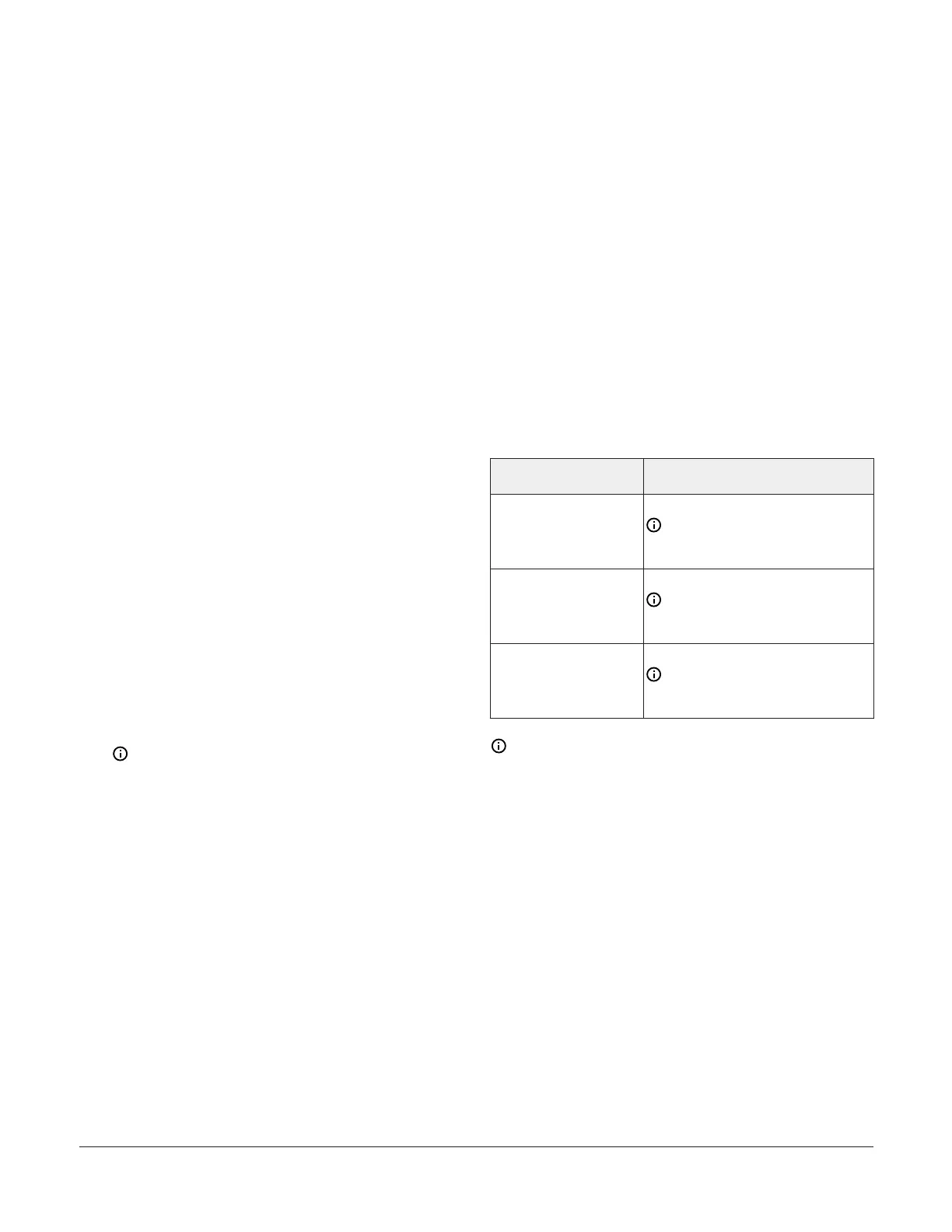
Setting the device address
Metasys equipment controllers are master devices
on MS/TP (FC or SA) buses. Before you operate
controllers on a bus, you must set a valid and
unique device address for each controller on the
bus. You set the CVM device address by setting the
positions of the Device Address rotary switches at
the top of the controller. See CVM03050 physical
features.
The following table describes the valid rotary
switch device addresses for communications bus
applications.
FC bus communication
mode
Valid device address range
Wired MS/TP
communication
4-127
Note: Addresses 0-3 are
reserved and not for use on
equipment controllers.
Zigbee wireless
communication
4-127
Note: Addresses 0-3 are
reserved and not for use on
equipment controllers.
N2 communication
1-254
Note: Addresses 0 and 255 are
reserved and not for use on
equipment controllers.
Note: The controller auto-detects if the
communication protocol is MS/TP, Zigbee
Wireless, or N2 on the FC Bus.
The device address is a decimal address set using
three rotary switches. The numbers are ordered
from left to right, most significant bit (MSB) to
least significant bit (LSB) when the controller is
oriented as shown in Figure 1. In the following
figure, the switches are set to 1 2 3, designating this
controller's device address as 123.
M4-CVM03050 VAV Controllers Installation Guide16