Parts included
• One CVM03050 controller with removable terminal
blocks (Input/Output, Power, FC, and SA bus are
removable)
• One installation instructions sheet
• One self-drilling No. 10 x 25 mm (1 in.) screw
Materials and special tools needed
• Small, straight-blade screwdriver for securing
wires in the terminal blocks
• 8 mm (5/16 in.) wrench or 10 mm (3/8 in.) 12-point
socket to tighten the square coupler bolt
• Several shims or washers to mount the CVM
• Power screwdriver, 100 mm (4 in.) extension
socket, punch, drill, and 3.5 mm (9/64 in.) drill bits
to mount the CVM
• Pliers to open and close the damper
• Required length of 3.97 mm (5/32 in.) ID
pneumatic tubing and barbed fittings
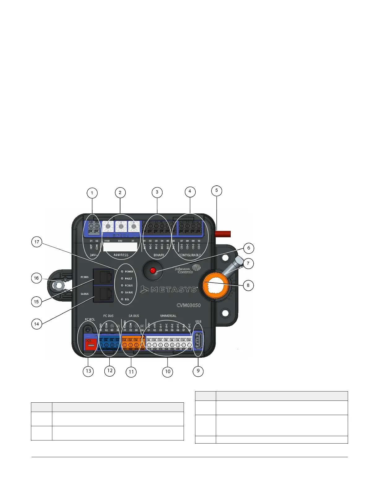
CVM03050 physical features
The following figure displays the physical features of CVM03050, and the accompanying table provides a
description of the physical features and a reference to further information where required.
Figure 1: CVM03050 physical features
Table 1: CVM03050 physical features
Physical features: description and references
1
Supply Power Terminal Block: Gray terminal; 24 VAC,
Class 2 (see Supply power terminal block)
2
Device Address Rotary Switches (see Setting the device
address)
Table 1: CVM03050 physical features
Physical features: description and references
3
Binary Output (BO) Terminal Block: Black terminals; 24
VAC Triacs (see Table 5)
4
Configurable Outputs (CO) Terminal Block: Black
terminals; can be defined as Voltage Analog Output (0–
10 VDC) or Binary Output (24 VAC Triac) (see Table 5)
5 Dual Port Fitting
M4-CVM03050 VAV Controllers Installation Guide2