Table 1: CVM03050 physical features
Physical features: description and references
6 Manual Override Button (see Mounting)
7 Coupler Bolt
8 Controller Coupler (see Mounting)
9
Universal Serial Bus (USB) 2.0 Host Type A Port
Note: The USB feature is not currently supported.
10
Universal Inputs (UI) Terminal Block: White terminal;
can be defined as one of the following (see Table 5):
Voltage Analog Input (0–10 VDC)
Resistive Analog Inputs (0–600k ohm): 0–2k
Potentiometer (see Table 5)
RTD: 1k Nickel, 1k Platinum, or A99B SI
NTC: 10K Type L (10K Johnson Controls Type II is
equivalent to Type L) or 2.252K Type II
Dry Contact Binary Input
11
Sensor Actuator (SA) Bus Terminal Block: Orange
terminal (see SA bus terminal block)
12
Field Controller (FC) Bus Terminal Block: Blue terminal;
may also be used for N2 connections, see FC bus
terminal block (or N2 protocol as required)
13
EOL (End-of-Line) Switch (see Setting the End-of-Line
(EOL) switch)
14
SA Bus Port: RJ-12 6-Pin Modular Jack (see Modular
ports)
15
FC Bus Port: RJ-12 6-Pin Modular Jack (see Modular
ports)
16 Captive Spacer and Screw
17 LED Status Indicators (see LED Table)
Mounting
Observe the following guidelines when mounting a
CVM controller:
• Ensure that the mounting surface can support the
CVM and any user-supplied enclosure.
• Mount the CVM on a hard, even surface whenever
possible.
• Use shims or washers to mount the CVM securely
and evenly on the mounting surface.
• Mount the CVM in an area free of corrosive
vapors that matches the ambient conditions
specified in the Technical specifications section.
• Provide sufficient space around the CVM for cable
and wire connections and adequate ventilation
through the controller (at least 50 mm [2 in.]
on the top, bottom, sides, and front of the
controllers).
• Do not mount the CVM in areas where
electromagnetic emissions from other
devices or wiring can interfere with controller
communication.
• Avoid mounting the CVM on surfaces with
excessive vibration.
Important: When the air supply to the VAV
box is below 10°C (50°F), make sure that any
condensation on the VAV box, particularly
on the damper shaft, does not enter the
CVM electronics. Mount the CVM vertically
above the damper shaft to allow any shaft
condensation to fall away from the controller.
Additional measures may be required in some
installations.
On panel or enclosure mount applications, observe
these additional guidelines:
• Do not install the CVM in an airtight enclosure.
• Mount the CVM so that the enclosure walls do not
obstruct cover removal or ventilation through the
controller.
• Mount the CVM so that the power transformer
and other devices do not radiate excessive heat to
the controller.
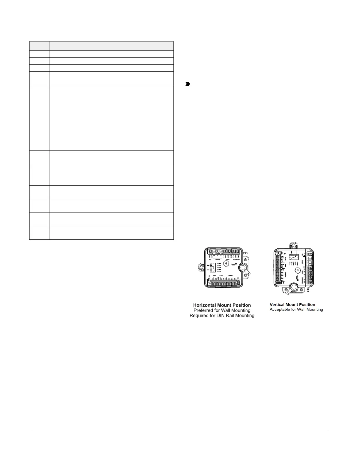
Figure 2: Controller mounting positions
To mount the CVM controllers, complete the
following steps:
1. Set all the switches on the equipment controller
to their known settings.
2. Place the CVM controller in the proper
mounting position on the damper shaft so that
the wiring connections are easily accessible.
Make sure the controller base is parallel to the
VAV box (perpendicular to the damper shaft).
If needed, use a spacer to offset tipping of the
controller caused by the shaft bushings.
M4-CVM03050 VAV Controllers Installation Guide 3