Communications bus and supply power
wiring guidelines
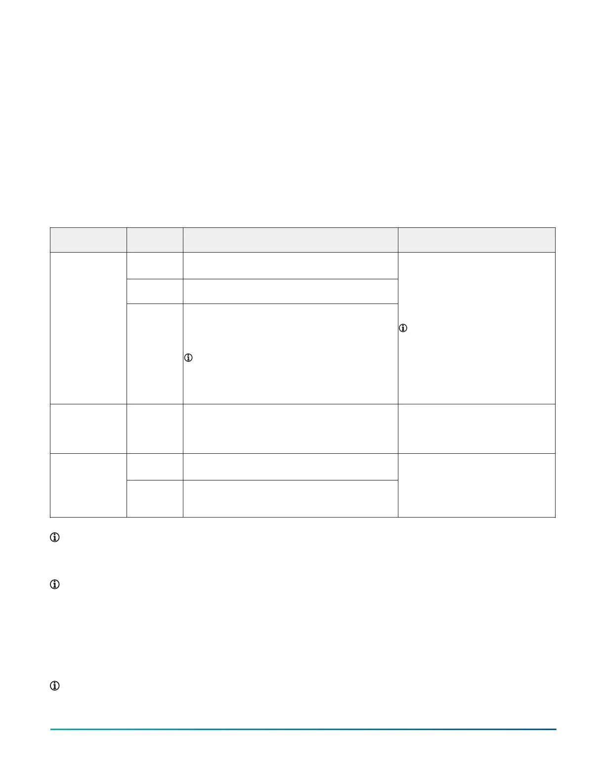
Table 5 provides information about the functions, ratings,
and requirements for the communication bus and supply
power terminals. The table also provides guidelines for
wire sizes, cable types, and cable lengths for wiring the
expansion module's communication bus and supply
power.
In addition to the guidelines in Table 5, observe the
following guidelines when wiring an FC bus, SA bus, or the
24 VAC supply power:
• Run all low-voltage wiring and cables separate from
high-voltage wiring.
• All SA and FC bus cables, regardless of wire size, should
be twisted, insulated, stranded copper wire.
• Shielded cable is strongly recommended for all SA and
FC bus cables.
• Refer to the MS/TP Communications Bus Technical
Bulletin (LIT-12011034) for detailed information
regarding wire size and cable length requirements for
FC and SA buses.
Table 5: Communications bus and supply power terminal block functions, ratings, requirements, and cable
guidelines
Terminal block/
Port label
Terminal
labels
Function, electrical ratings/Requirements Recommended cable type
+
-
FC or SA Bus Communications
COM Signal Reference (Common) for FC or SA Bus
communications
FC BUS
or
SA BUS
SHD
or
PWR
SHD on FC Bus: Isolated terminal (optional shield drain
connection
PWR on SA Bus: 15 VDC power lead connection.
(Maximum total current draw for SA bus is 240 mA.)
Note: The PWR terminal on an XPM expansion
module does not supply 15 VDC. The SA bus
supervisor (CGE,CGM, CVE, CVM, FAC, FEC, VMA)
supplies 15 VDC to devices on the SA bus requiring
power.
FC Bus: 0.6 mm (22 AWG) stranded,
3-wire twisted, shielded cable
recommended.
SA Bus: 0.6 mm (22 AWG) stranded, 4-
wire (2 twisted-pairs), shielded cable
recommended.
Note: On the SA Bus, the + and
- wire are one twisted pair, and
the COM and PWR are the second
twisted pair of wires.
SA/FC BUS
(Port)
RJ-12 6-Position Modular Connector provides:
• FC or SA Bus Communications
• FC or SA Bus Signal Reference and 15 VDC
Common
24 AWG 3-pair CAT 3 Cable <30.5 m (100
ft)
HOT 24 VAC Power Supply - Hot
Supplies 20–30 VAC (Nominal 24 VAC)
24V~
COM 24 VAC Power Supply - Common
(Isolated from all other Common terminals on
controller.)
0.8 mm to 1.0 mm
(18 AWG) 2-wire
Note: See table labeled Cable length guidelines for
recommended wire sizes for low-voltage (<30 V) Inputs
and Outputs to determine wire size and cable lengths
for cables.
Note: The SA Bus and FC Bus wiring
recommendations in this table are for MS/TP
bus communications at 38,400 baud. For more
information, refer to the MS/TP Communications Bus
Technical Bulletin (LIT-12011034).
Termination diagrams
A set of Johnson Controls termination diagrams provides details for wiring inputs and outputs to the expansion modules.
See the figures in this section for the applicable termination diagrams.
Note: References to the analog output apply to the XPM09090 model only.
M4-XPM Expansion Modules Installation Guide10