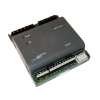
2. Underneath the terminal block, in the small gap
between the bottom of the terminal block and
the circuit board, insert the flat blade of the
screwdriver.
Figure 12: Terminal block
3. To detach the left-hand side of the terminal block,
position the flat blade underneath the terminal
block to the left, and push down the screwdriver
handle. When you do this, you are using the
screwdriver as a lever to pry up the terminal block.
4. To detach the right-hand side of the terminal block,
position the flat blade underneath the terminal
block to the right, and push down the screwdriver
handle.
5. If necessary, repeat steps 3 and 4 until the terminal
block is removed.
Removing the expansion module cover
About this task:
Important: Electrostatic discharge can damage
expansion module components. Use proper
electrostatic discharge precautions during
installation, setup, and servicing to avoid damaging
the expansion module.
Important: Disconnect all power sources to
the expansion module before removing cover
and changing the position of any jumper or the
EOL switch on the expansion module. Failure to
disconnect power before changing a jumper or
EOL switch position can result in damage to the
expansion module and void any warranties.
The expansion module cover is held in place by four
plastic latches that extend from the base and snap into
slots on the inside of the housing cover.
To remove the expansion module cover, complete the
following steps:
1. Place your fingertips under the two cover lift tabs
(Physical features) on the sides of the housing
cover and gently pry the top of the cover away
from the base to release the cover from the two
upper latches.
2. Pivot the top of the cover further to release it from
the lower two latches.
3. Replace the cover by placing it squarely over the
base, and then gently and evenly push the cover
on to the latches until they snap into the latched
position.
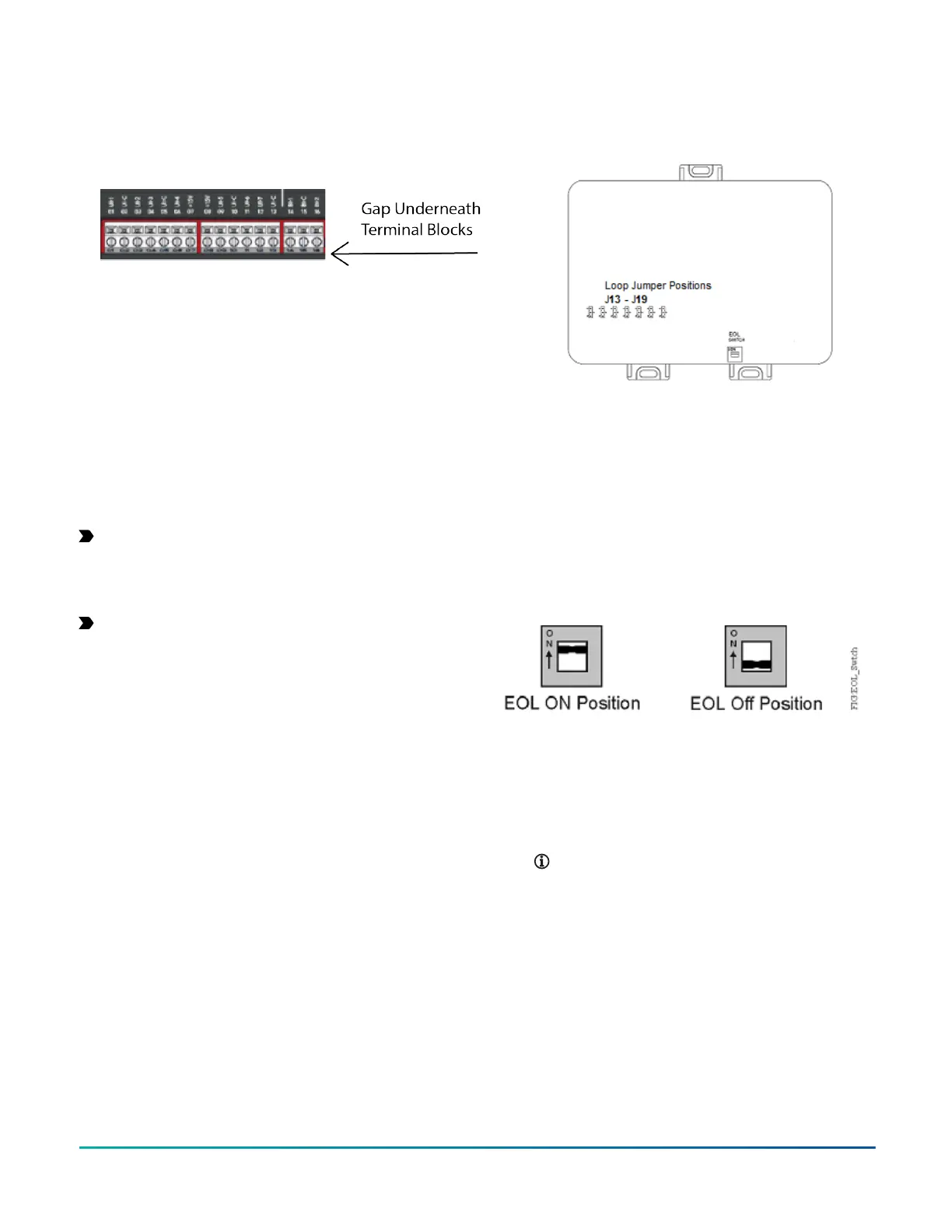
Figure 13: XPM with cover removed showing EOL
switch and jumper positions (XPM09090 model shown)
Setting the End-of-Line (EOL) switch
About this task:
Each XPM expansion module has an EOL switch, which,
when set to ON (up), sets the expansion module as a
terminating device on the bus. See figure labeled XPM with
cover removed showing EOL switch and jumper positions for
the EOL switch location. The default EOL switch position is
OFF (down).
Figure 14: End-of-Line switch positions
To set the EOL switch on an expansion module, complete
the following steps:
1. Determine the physical location of the expansion
module on the SA or FC bus.
2. Determine if the expansion module must be set as
a terminating device on the bus.
Note: SA and FC buses have different EOL
termination rules. For detailed information
about EOL termination rules and EOL switch
settings, refer to the MS/TP Communications
Bus Technical Bulletin (LIT-12011034).
3. If the expansion module is a terminating device
on the FC bus, set the EOL switch to ON. If the
expansion module is not a terminating device on
the bus, set the EOL switch to Off.
When an expansion module is connected to power
with its EOL switch set to ON, the amber EOL LED
on the controller cover is illuminated.
M4-XPM Expansion Modules Installation Guide 17