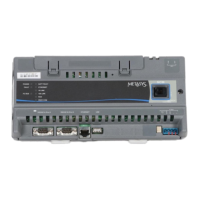
LED status and states
Table 10: Status LEDs and description of LED states
LED label LED color Normal LED state Description of LED states
POWER Green On Steady Off Steady = No Supply Power or the controller’s polyswitch/resettable fuse is
open. Check Output wiring for short circuits and cycle power to controller.
On Steady = Power Connected
FAULT Red Off Steady Off Steady = No Faults
On Steady = Device Fault; no application loaded
Blink - 2 Hz = Startup in progress, not ready for normal operation
Rapid blink = SA Bus communications issue
SA/FC BUS Green Blink - 2 Hz Blink - 2 Hz = Data Transmission (normal communication)
Off Steady = No Data Transmission
On Steady = Communication lost, waiting to join communication ring
EOL Amber Off (Except on
terminating
devices)
On Steady = EOL switch in ON position
Off Steady = EOL switch in Off position
Ordering information and accessories
The following tables provide the product code number and description for the XPM models and accessories.
Table 11: XPM Series ordering information
Product code number Description
M4-XPM04060-0 10-point Input/Output Expansion Module
Includes: MS/TP communication; 10 points (3 UI, 1 BI, 4 CO, 2 BO); 24VAC input
M4-XPM09090-0 18-point Input/Output Expansion Module
Includes: MS/TP communication; 18 points (7 UI, 2 BI, 4 CO, 2 AO, 3 BO); 24VAC input
M4-XPM18000-0 18-point Input Expansion Module
Includes: MS/TP communication; 18 points (18 BI); 24VAC input
Table 12: XPM series accessories (order separately)
Product Code Number Description
TL-CCT-0 Controller Configuration Tool (CCT) software
MS-FCP-0 Metasys Equipment Controller Firmware Package Files required for CCT
Mobile Access Portal (MAP) Gateway Refer to the Mobile Access Portal Gateway Catalog Page (LIT-1900869) to identify the
appropriate product for your region.
WRZ Series Wireless Room Sensors Refer to the WRZ Series Wireless Room Sensors Product Bulletin (LIT-12011653) for
specific sensor model descriptions.
WRZ-7860-0 Receiver for One-to-One Wireless Room Sensing Systems - functions with WRZ
Series Sensors
Refer to the WRZ-7860 Receiver for One-to-One Wireless Room Sensing Product
Bulletin (LIT-12011640) for a list of available products.
WRZ-SST-120 Wireless System Survey Tool. For use with the lower power 10mW WRZ and
WRZ-7860 systems.
Refer to the WRZ-SST-120 Wireless Sensing System Tool Installation Guide
(24-10563-55) for usage instructions.
ZFR-HPSST-0 Wireless System Survey Tool. For use with the higher power WRG1830/ZFR183x
System and lower power WRZ Sensors (10mW). Refer to the ZFR-HPSST-0 Wireless
Sensing System Tool Installation Guide (Part No. 24-11461-00012) for usage
instructions.
M4-XPM Expansion Modules Installation Guide 19