Setting the UI current loop jumpers
CAUTION
Risk of Electric Shock:
Disconnect supply power to the expansion module
before attempting to adjust the UI current loop
jumpers. Failure to disconnect the supply power may
result in electric shock.
ATTENTION
Mise En Garde: Risque de décharge électrique:
Débrancher l'alimentation de l'controller avant tout
réglage du UI current loop jumpers. Le non-respect de
cette précaution risque de provoquer une décharge
électrique.
The UI current loop jumpers are on the circuit board
under the expansion module cover near the UI terminals
(Figure 13). When a UI is defined (in the system software)
as a 4-20 mA Analog Input, set the UI's current loop
jumper to the Enabled position (Figure 15).
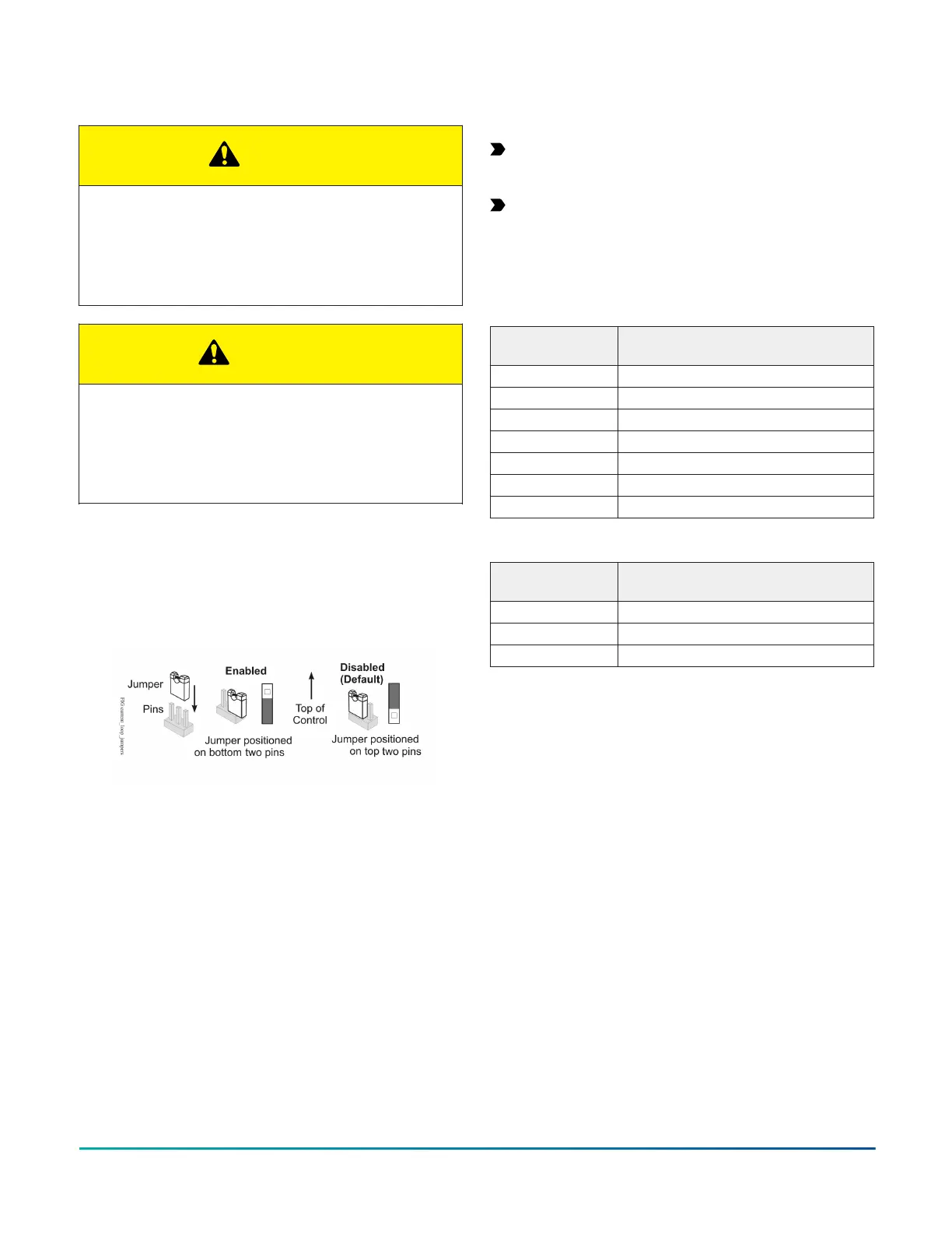
Figure 15: UI Current loop jumper positions
Setting the current loop jumper to the Enabled position,
connects an internal 100 ohm resistor across the UI
terminals, which maintains the 4-20 mA current loop
circuit even when power to the expansion module is
interrupted or off.
Important: Current Loop jumpers must be in the
Disabled (default) position for all UIs that are not set
up to operate as 4-20 mA analog inputs.
Important: A current loop jumper must be in the
Enabled position to maintain a closed 4-20 mA
current loop.
The following tables identify the current loop switches
associated with each UI on the XPM09090 and XPM04060
models.
Table 8: XPM09090 UI Inputs and jumper labels
Universal Input
label
Jumper label on circuit board
UI-1 J13
UI-2 J14
UI-3 J15
UI-4 J16
UI-5 J17
UI-6 J18
UI-7 J19
Table 9: XPM04060 UI Inputs and jumper labels
Universal Input
label
Jumper label on circuit board
UI-1 J10
UI-2 J11
UI-3 J12
Commissioning
You commission expansion modules with the Controller
Configuration Tool (CCT) software using either Mobile
Access Portal (MAP) Gateway, a ZFR wireless dongle, or in
passthrough mode when connected to a Network Engine.
Refer to the Controller Tool Help (LIT-12011147) for detailed
information on commissioning expansion modules.
Troubleshooting expansion modules
Observe the Status LEDs on the front of the expansion module. Table 10 provides LED status indicator information for
troubleshooting the expansion module. To troubleshoot a local controller display, refer to the DIS1710 Local Controller
Display Technical Bulletin (LIT-12011270) or Local Controller Display User Guide (LIT-12013762).
M4-XPM Expansion Modules Installation Guide18