Addressable Intelligent Module—AIM-200 Addressable Intelligent Module 11
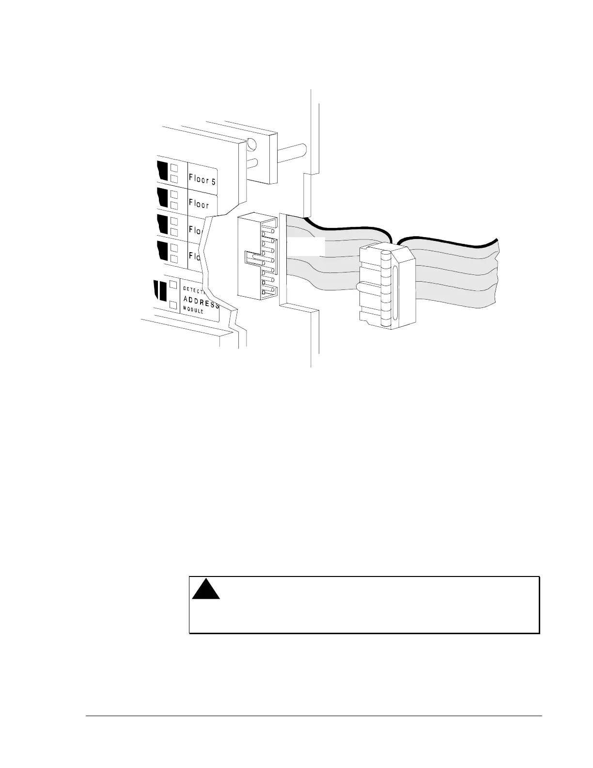
4. Connect the ribbon cable. See Figure 5.
Figure 5: Connecting the Ribbon Cable
Connect the alarm bus cable following the steps below. Use the alarm bus
cable (Part No. 71033) included with the AIM-200.
1. Remove the 2-pin connector on one end of the cable.
2. Separate and strip the wires, leaving about half an inch of bare wire
exposed.
3. Connect wires to Terminals 14 and 15 on the CPU.
4. Connect the other end of the trouble cable to the left-most 2-pin
terminal on the bottom left-hand corner of the AIM-200. If additional
AIM-200s are employed, see Figure 6.
!
CAUTION: Do not connect any other device or circuit to the
alarm relay contacts on the CPU-2000 while the alarm
bus cable (Part No. 71033) is installed in the system.
Connecting the
Alarm Bus Cable