Addressable Intelligent Module—AIM-200 Addressable Intelligent Module 41
AIM-200 Power Requirements
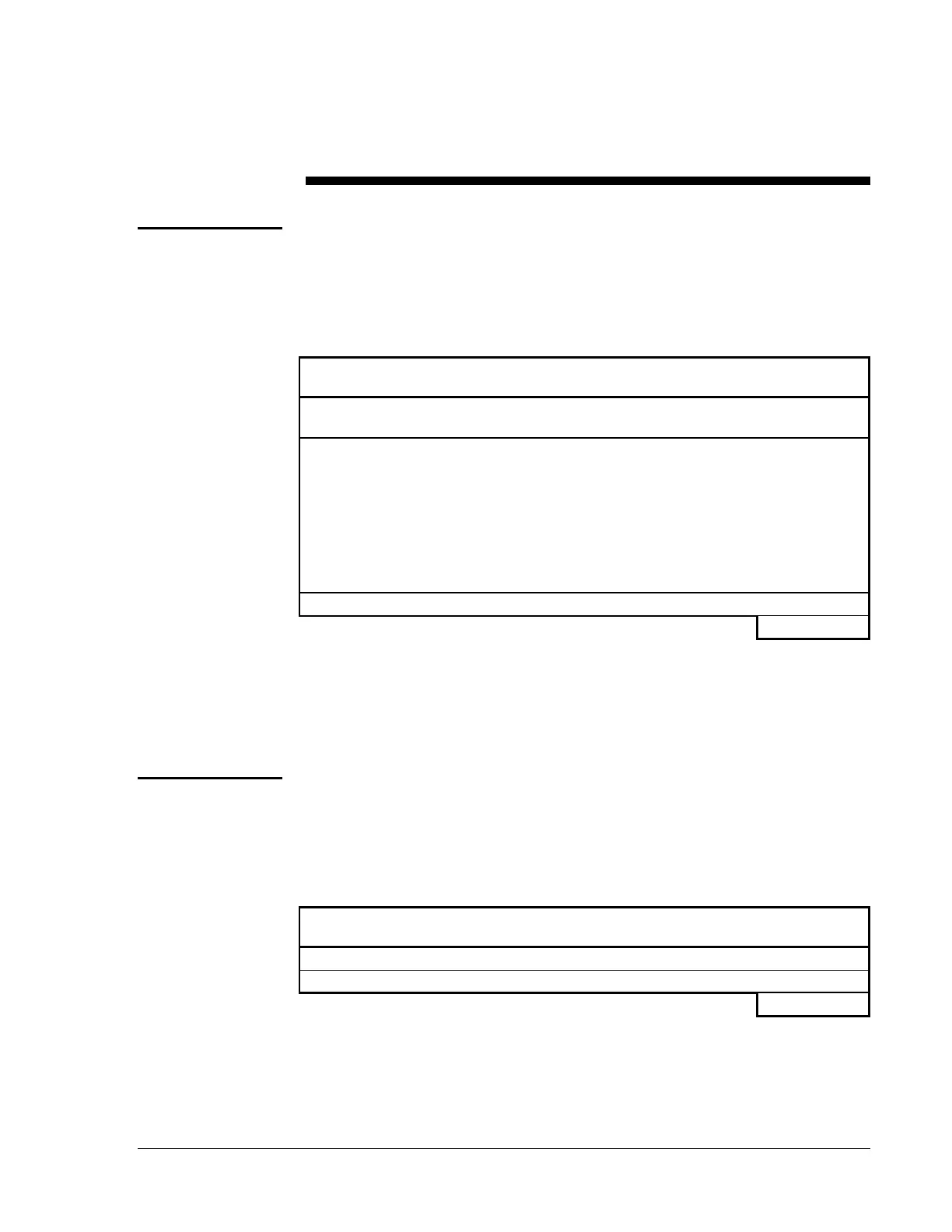
Use Table 2 to determine the amount of current drawn by the AIM-200(s)
during non-alarm conditions. Place the total standby current obtained in
the Installing the FC-2000 Technical Bulletin in this document when
calculating secondary power standby requirements for the control panel.
Table 2: Standby Regulated Power Requirements
Device Type Device
Number
Current
(amps)
Total Current
AIM-200
(Note 1)
[ ] X 0.050 =
Detectors and
Modules
1551J, 2551J,
2551TH,
5551J,
M500MJ,
M501MJ,
M510CJ,
BGX-101L
[ ] X 0.000210 =
M500XJ
[ ] X 0.000420 =
Total Standby Current = amps
1. Maximum number of AIM-200s is determined by power supply
loading limits in the Installing the FC-2000 Technical Bulletin in this
manual but may never exceed the following limits: 10 with the
MPS-24A; 2 with the MPS-24B.
Use Table 3 to determine the amount of current drawn by the AIM-200(s)
in the FC-2000 during an alarm. Place the Total Alarm Current obtained in
the Installing the FC-2000 Technical Bulletin in this manual when
calculating regulated requirements in the alarm state for the control panel.
Table 3: Alarm State Regulated Power Requirements
Device Type Device
Number
Current
(amps)
Total Current
AIM-200
[ ] X 0.075 =
Total AIM-200 Current (from Table 2) =
Total Alarm Current = amps
Regulated
Power Required
in Standby
Regulated
Power Required
in Alarm