46 Addressable Intelligent Module—AIM-200 Addressable Intelligent Module
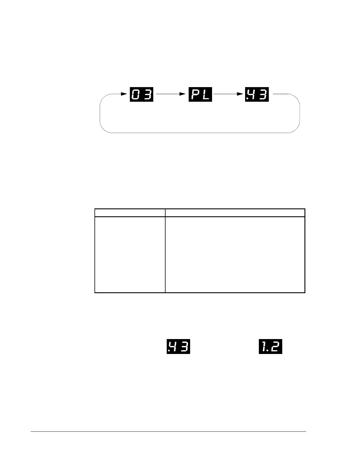
When the Display Status mode is entered, the digital display will repeatedly
flash the address, type and sensitivity of the detector assigned to the lowest
address. The user can scroll through all detectors using the
STEP-FORWARD and STEP-REVERSE switches. The SKIP switch
advances addresses rapidly.
Figure 37: Displaying the Status of Intelligent Detectors
Detector Device Type/Status
The Device Type/Status field displays two characters for intelligent
detectors, outlined below.
Table 6: Device Type/Status Field Display
Left Digit Right Digit
P = Photo Detector Blank = Normal Sensitivity
I = Ion Detector L = Low Sensitivity
H = Heat Detector H = High Sensitivity
A = Alarm
F = Fault (Maintenance Alert)
d = Disabled
E = Error--No response from a device (the AIM-200 is
programmed for a device that is in trouble or not physically
installed on the loop).
U = Unsatisfactory (failed automatic detector test).
The percent of alarm threshold for detectors are displayed with a decimal
point as illustrated below.
Figure 38: Alarm Threshold Percentage
Displaying the
Status of
Intelligent
Detectors
Alarm Threshold
Percentage