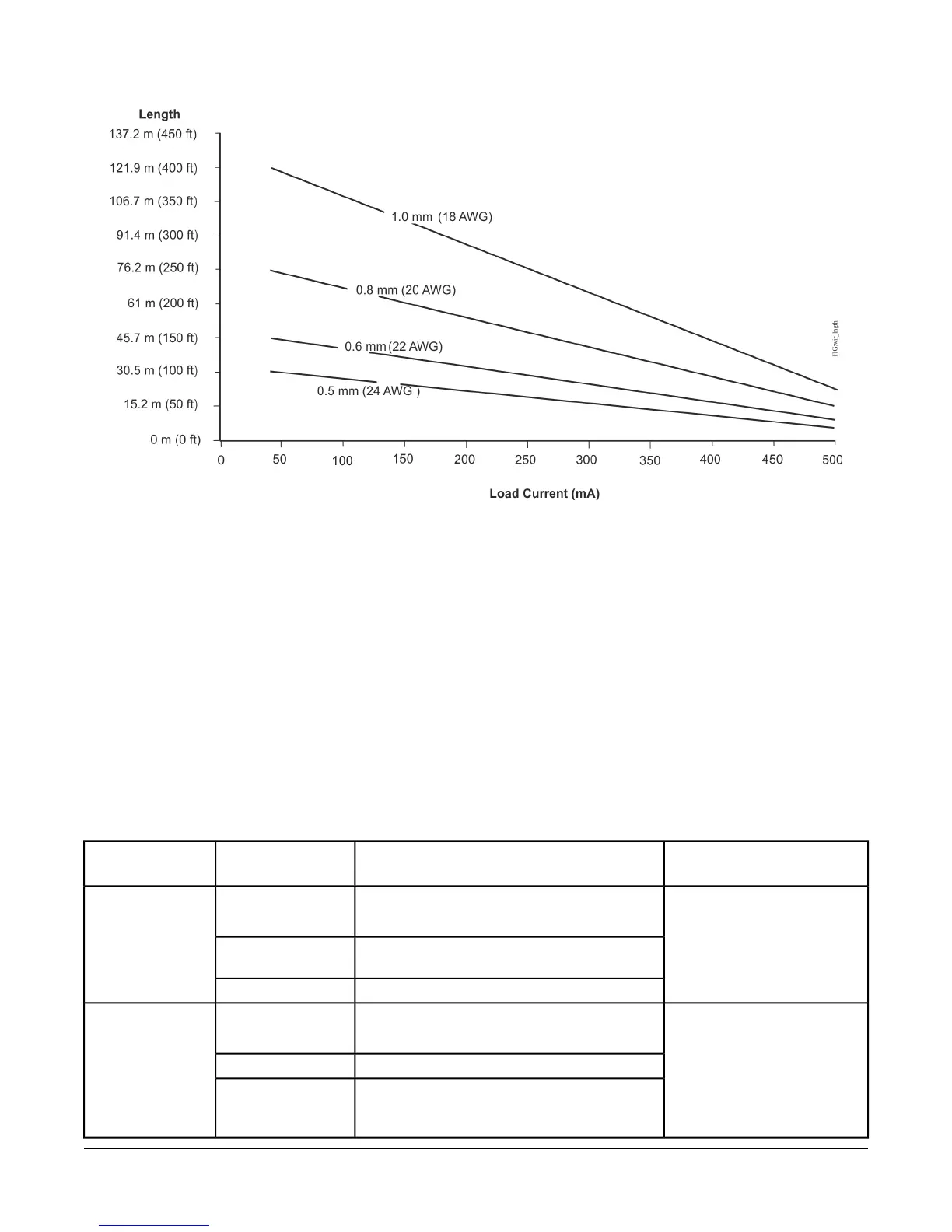
Figure 7: Maximum Wire Length by Current and Wire Size
FC and SA Bus and Supply
Power Wiring Guidelines
Table 4 provides information about terminal block
functions, ratings, and requirements.
Table 4 also provides wire size, cable type, and cable
length guidelines for wiring the VMA communication
buses and supply power.
In addition to the guidelines in Table 4, observe these
guidelines when wiring the SA/FC Buses and supply
power:
• Run all low-voltage wiring and cables separate from
high-voltage wiring.
• All FC and SA Bus cables, regardless of wire size,
should be twisted, insulated, stranded copper wire.
• Shielded cable is strongly recommended for all FC
and SA Bus cables.
•
Refer to the MS/TP Communications Bus Technical
Bulletin (LIT-12011034) for detailed information
regarding wire size and cable length requirements for
the FC and SA buses.
Table 4: Communication Bus and Supply Power Terminal Blocks, Functions, Ratings, Requirements, and
Cables
Recommended Cable Type
1
Function, Electrical Ratings/RequirementsTerminal LabelsTerminal
Block/Port Label
0.6 mm (22 AWG) stranded,
3-wire twisted, shielded cable
recommended
FC Bus Communications+
-
FC BUS
2
Signal Reference (Common) for bus
communications
COM
Isolated terminal (optional shield drain connection)SHLD
0.6 mm (22 AWG) stranded,
4-wire (2 twisted-pairs), shielded
cable recommended
The + and - wires are one
twisted pair and the COM and
SA PWR are the second twisted
pair of wires.
SA Bus Communications+
-
SA BUS
2
SA Bus Signal Reference and 15 VDC CommonCOM
15 VDC Supply Power for Devices on the SA BusSA PWR
13VMA1610 and VMA1620 Variable Air Volume Controllers Installation Instructions

 Loading...


