To ensure the best bus performance, set sequential
device addresses with no gaps in the device address
range (for example, 4, 5, 6, 7, 8, and 9). The
controllers do not need to be physically connected
on the bus in their numerical device address order.
4. Write each controller's device address on the white
label below the DIP switch block on the controller's
cover.
Refer to the MS/TP Communications Bus Technical
Bulletin (LIT-12011034) for more information on field
controller device addresses and how to set them on
MS/TP buses.
Table 5 describes the valid FC Bus and SA Bus devices
addresses for Johnson Controls® MS/TP communications
bus applications.
Table 5: SA/FC Bus Device Address Descriptions
Address DescriptionDevice
Address
Reserved for FC Bus Supervisory Controller.
Not valid for controllers.
0
(Switch 128
Off)
Reserved for peripheral devices. Not valid for
controllers.
1 to 3
(Switch 128
Off)
Valid for MS/TP Master controllers on a
hardwired SA Bus or FC Bus.
4 to 127
(Switch 128
Off)
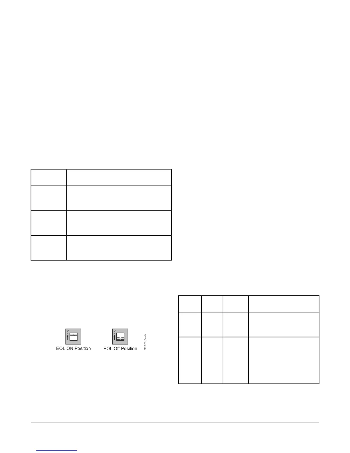
Setting the EOL Switch
Each controller has an End-of-Line (EOL) switch, which,
when set to ON (up), sets the VMA controller as a
terminating device on the bus. See Figure 2 for the EOL
switch location on the controller. The default EOL switch
position is off (down).
Figure 9: EOL Switch Positions
To set the EOL switch on a VMA controller:
1. Determine the physical location of the VMA controller
on the SA or FC Bus.
2. Determine if the controller must be set as a
terminating device on the bus.
Note: The EOL termination rules for SA Buses and
FC Buses are different. Refer to the MS/TP
Communications Bus Technical Bulletin
(LIT-12011034) for detailed information
regarding EOL termination rules and EOL
switch settings on SA and FC Buses.
3. If the controller is a terminating device on the SA Bus
or FC Bus, set the EOL switch to ON. If the controller
is not a terminating device on the bus, set the EOL
switch to off.
Commissioning
Use the following procedure to commission the VMA
controller:
1. Download the control application to the VMA controller
using the Metasys Controller Tool. Refer to the
Controller Tool Help (LIT-12011147).
2. Commission the VAV Box. Refer to the Controller
Tool Help (LIT-12011147).
3. Balance the airflow on the VAV box. Refer to the VAV
Balancing Tool Technical Bulletin (LIT-12011087).
4. Perform commissioning checkout procedures. Refer
to the Controller Tool Help (LIT-12011147).
Troubleshooting
Table 6 provides LED status indicator information to help
troubleshoot the VMA controller.
Table 6: VMA16 Series Controller Status LEDs
Descriptions of LED
States
Normal
State
LED
Color
LED
Label
Off Steady = No power
On Steady = Power is supplied
by primary voltage.
On
Steady
GreenPOWER
Blink - 2 Hz = Download or
startup in progress; not ready
for normal operation
Off Steady = No faults
On Steady = Device fault or no
application loaded
Off
Steady
RedFAULT
15VMA1610 and VMA1620 Variable Air Volume Controllers Installation Instructions

 Loading...


