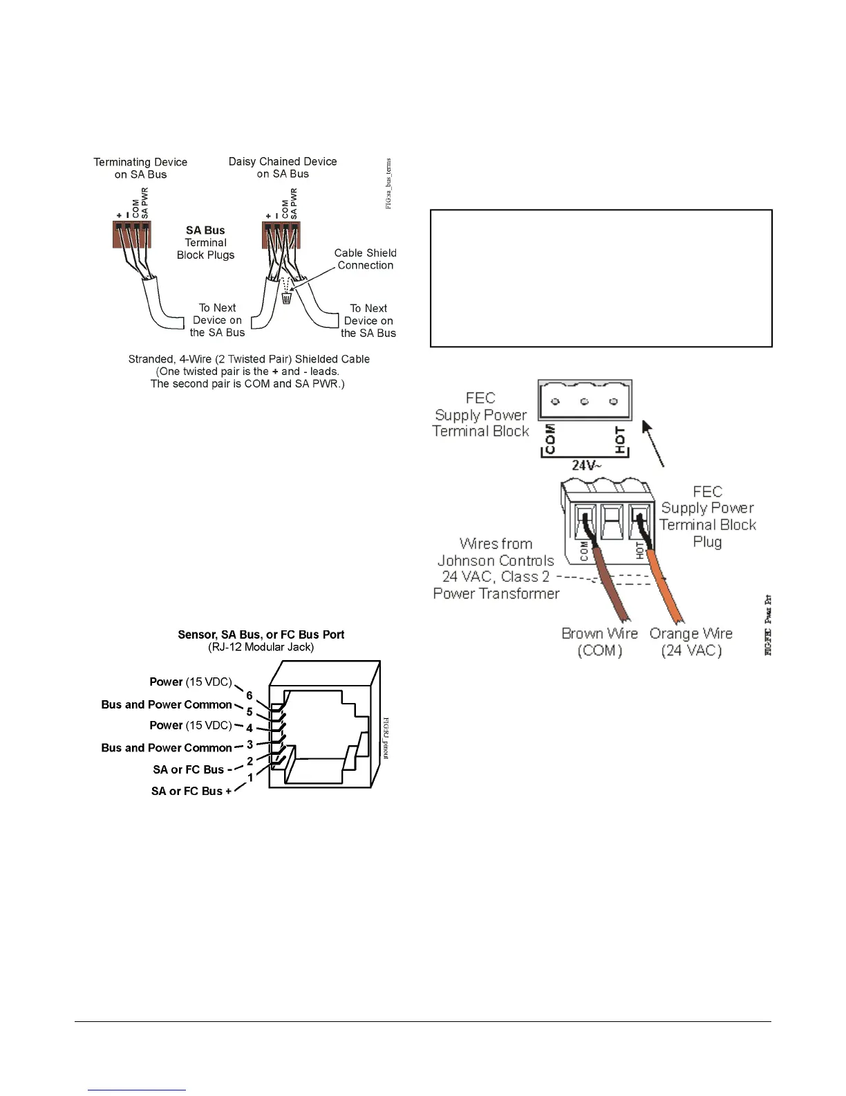
Figure 4: SA Bus Terminal Block Wiring
Sensor Port
The Sensor (SA Bus) port on the left side of the VMA
(Figure 2) is an RJ-12, 6-position modular jack that
provides a connection for the VAV Balancing Tool,
specified network sensors, or other SA Bus devices with
RJ-12 plugs.
The Sensor port is connected internally to the SA Bus
terminal block. See Table 4 for more information. The
Sensor Port pin assignment is shown in Figure 5.
Figure 5: Pin Number Assignments for Sensor, SA
Bus, and FC Bus Ports on VMAs
Supply Power Terminal Block
The 24 VAC supply power terminal block is a gray,
removable, 3-terminal plug that fits into a board-mounted
jack on the bottom right of the VMA.
Wire the 24 VAC supply power wires from the transformer
to the HOT and COM terminals on the terminal plug as
shown in Figure 6. The middle terminal on the supply
power terminal block is not used. See Table 4 for more
information.
The supply power wire colors may be different on
transformers from other manufacturers. Refer to the
transformer manufacturer’s instructions and the project
installation drawings for wiring details.
Important: Connect 24 VAC supply power to the VMA
and all other network devices so that
transformer phasing is uniform across the
network devices. Powering network devices
with uniform 24 VAC supply power phasing
reduces noise, interference, and ground
loop problems. The VMA does not require
an earth ground connection.
Figure 6: 24 VAC Supply Power Terminal Block Wiring
To wire the VMA controller:
1. Terminate wiring per engineering drawings.
2. Wire network sensors and other devices to the VMA's
SA Bus.
3. Wire the FC Bus in a daisy chain.
4. Ensure that the VMA’s device address DIP switches
are set to the appropriate device address. (See
Setting the Device Address.)
5. Connect the VMA controller to 24 VAC, Class 2
power.
6VMA1610 and VMA1620 Variable Air Volume Controllers Installation Instructions

 Loading...


