N
egative temperature cold room with three phase defrost and evaporator fan
Selection table:
Item code Power
supply
Compressor Evap.
Fan
Cond. Fan /
Door frame
heater
Defrost Cabinet
Size
Shipping
weight
V ac
Φ
ΦΦ
Φ
Power
AC-3 Amps Amps Amps modules Kg
CR-NFDT150-1
400 3 1,5 kW 3,5 3 x 2 5 3 x 5 36 5,3
CR-NFDT400-1
400 3 4,0 kW 8,5 3 x 2 5 3 x 10 36 5,3
CR-NFDT750-1
400 3 7,5 kW 15,5 3 x 2 5 3 x 16 36 5,3
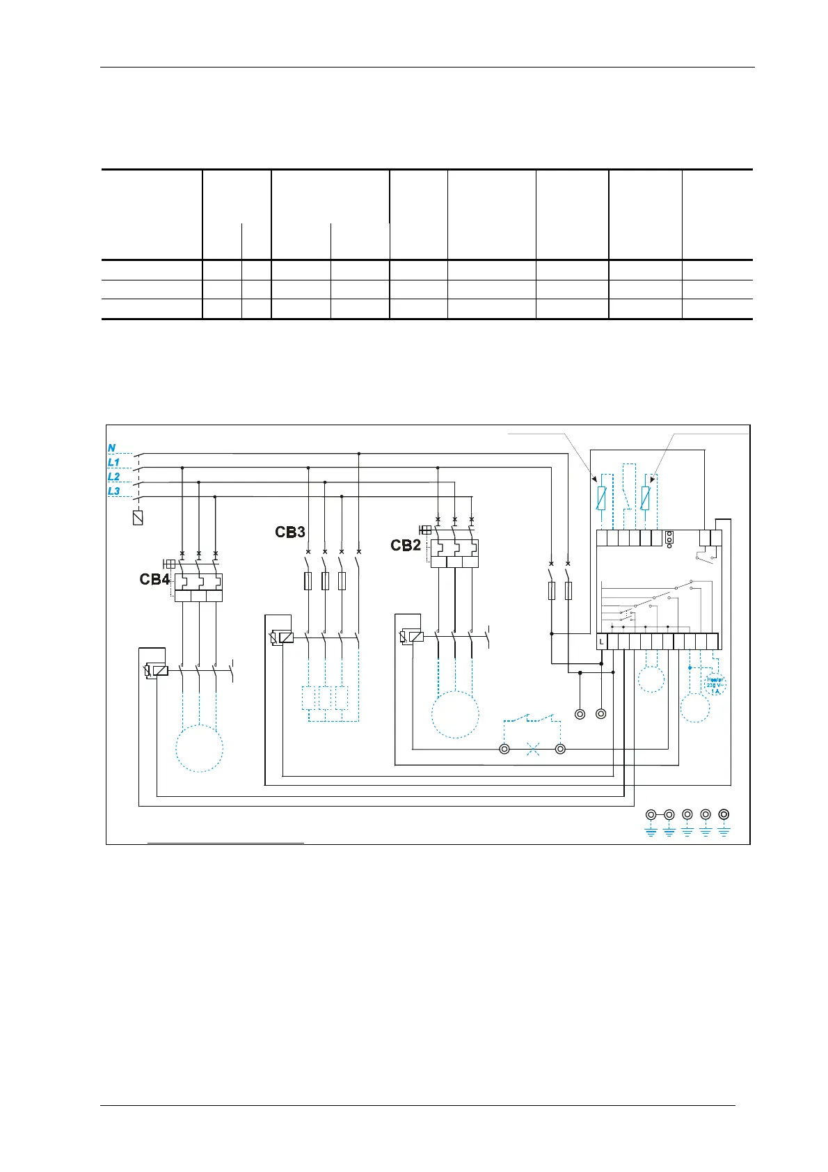
Wiring diagram
Valve
Pump
down
Defrost
230 V 3~
Fuses
reaker
Circuit
B
Circuit
~ 400 V
Breaker
3
C
o
n
t
a
c
t
o
r
A99
Contact
pump
down
A99
1L1 3L2 5L3
2T1 4T2 6T3
I> I> I>
A1 1L1 3L2 5L3
2T1 4T2 6T3A2
Compressor
3 ~ 400 Volts
MR15DR230
1011
B1 ADA B2 A
N 13 7 4NNNN4’
Alarm
230V~
0,5 A
8T4
7L4
21
22
Pressure
switch
HPBP
3’
1L1 3L2 5L3
2T1 4T2 6T3 8T4
7L4A1
A2
Circuit
Breaker
C
o
m
p
r
e
s
s
o
r
C
o
n
t
a
c
t
o
r
D
e
f
r
o
s
t
Defrost
Compressor
K1
C
B
1
K2
Ambient Sensor Evaporator Sensor
23
Cond. Fan /
Door frame
24
F1
Fuses
Main
Switch
WIRING DIAGRAM FOR:
CR-NFDT150-1 / CR-NFDT400-1 / CR-NFDT750-1
Circuit
~ 400 V
Breaker
3
C
o
n
t
a
c
t
o
r
1L1 3L2 5L3
2T1 4T2 6T3
I> I> I>
A1 1L1 3L2 5L3
2T1 4T2 6T3A2
Fan
8T4
7L4
F
a
n
Fan
K3
Q1
3 ~ 400 Volts
1L1
3L2
5L3
7L4
Negative temperature cold room- three phase Compressor, Defrost and Evaporator Fan
CR1 9
© 2010 Johnson Controls, Inc. Catalogue Section 9