N
egative temperature cold room with three phase defrost
Selection table:
Item code Power
supply
Compressor Evap.
Fan
Cond. Fan /
Door frame
heater
Defrost Cabinet
Size
Shipping
weight
V ac
Φ
ΦΦ
Φ
Power
AC-3 Amps Amps Amps Amps modules Kg
CR-NDT150-1
400 3 1,5 kW 3,5 3,2 4 3 x 5 24 4,1
CR-NDT250-1
400 3 2,5 kW 5,7 3,2 4 3 x 9 24 4,1
CR-NDT400-1
400 3 4,0 kW 8,5 4,8 6 3 x 10 24 4,1
CR-NDT550-1
400 3 5,5 kW 11,5 4,8 6 3 x 12 24 4,1
CR-NDT750-1
400 3 7,5 kW 15,5 4,8 6 3 x 16 24 4,1
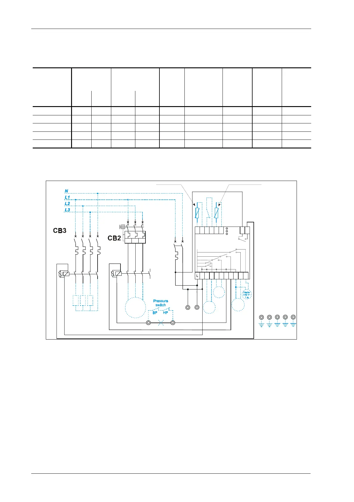
Wiring diagram:
Valve
Pump
down
Defrost
230 V 3~
reaker
1P+N
Circuit
B
Circuit
~ 400 V
Breaker
3
Contactor
Fan
230 Volts
A99
Contact
pump
down
A99
1L1 3L2 5L3
2T1 4T2 6T3
I>
I> I>
A1 1L1 3L2 5L3
2T1 4T2 6T3A2
Compressor
3 ~ 400 Volts
MR15DR230
1011
B1 ADA B2 A
N
13
7
4NNNN4’
13N
24N
Alarm
230V~
0,5 A
8T4
7L4
21
2121
21
22
2222
22
3’
1/ 2
3/ 4
5/6
2/1 4/3 6/5
1L1 3L2 5L3
2T1 4T2 6T3 8T4
7L4
A1
A2
Circuit
Breaker
4P
7/8
7/8
Compressor
Contactor
Defrost
Defrost
Compressor
K1
CB1
K2
Ambient Sensor Evaporator Sensor
23
Cond. Fan /
Door frame
24
Negative temperature cold room three phase Compressor and three phase Defrost models
8 CR1
Catalogue Section 9 © 2000 Johnson Controls, Inc.