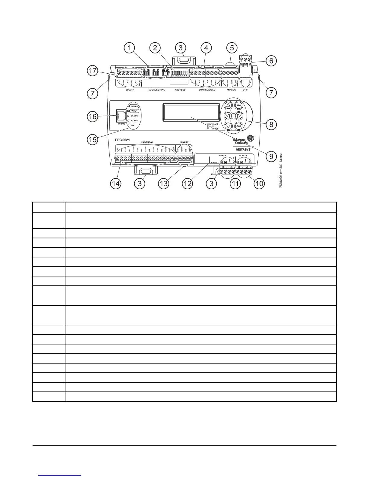
Figure 3: FEC2621 Physical Features
Table 1: FEC2621 Physical Features
Physical Feature: Description and ReferencesCallout
Binary Output (BO) Source Power Selection Jumper Pin Blocks, 3 – BO Jumper Pin Blocks. See Table 4 for more
information.
1
Device Address DIP Switch Block. See Setting the Device Addresses for more information.
2
Mounting Clip. See Mounting for more information.
3
Configurable Output (COs) Terminal Blocks. See Table 4 for more information.
4
Analog Outputs (AOs) Terminal Block. See Table 4 for more information.
5
24 VAC, Class 2 Supply Power Terminal Block. See Table 6 for more information.
6
Cover Lift Tab (One of Two). See Removing the Controller Cover for more information.
7
Display Navigation Buttons. See Setting Up an Integral or Local Display.
Note: Not available on all FEC models.
8
Liquid Crystal Display (LCD) Display Area
Note: Not available on all FEC models.
9
Field Controller (FC) Bus Terminal Block. (See FC Bus Terminal Block.)
10
Sensor Actuator (SA) Bus Terminal Block. (See SA Bus Terminal Block.)
11
Sensor Actuator (SA) Bus (RJ-12 6-pin Modular Jack). See Sensor Port.
12
Binary Input (BI) Terminal Block, 2 – Binary Inputs. See Table 4 for more information.
13
Universal Input (UI) Terminal Blocks, 6 – Universal Inputs. See Table 4 for more information.
14
LED Status Indicators. See Table 9 for more information.
15
Field Controller (FC) Bus Port (RJ-12 6-pin Modular Jack). See FC Bus Port for more information.
16
Binary Output (BO) Terminal Blocks. See Table 4.
17
4FEC26 Field Equipment Controllers Installation Instructions

 Loading...


