Network Control Module 300 Series Technical Bulletin 34
Standard Cables
Table 15 provides an overview of cables used with the NCM.
Table 15: Standard Cables
Description of Connectors
(Gender and Pin No.)
Commonly Used Names
NCM Device
Applies to Figures
IBM AT to Null Modem
(DTE-DTE)
Female DB9 Female DB9 9, 10, 16, 18
IBM AT to Modem
(Straight-through)
(DTE-DCE)
Female DB9 Male DB25 6, 11, 15, 21
IBM AT to Printer
(DTE-DCE)
Female DB9 Male DB25 12
IBM AT to Null Modem
(DTE-DTE)
Female DB9 Male DB25 w/ gender
changer (Female to
Female)
9, 17, 18
Notes: Figure 13, Figure 18, and Figure 19 are special cases requiring custom cables.
The NCM, Companion, and DX9100 RS232 ports have identical pinouts.
Standard null modem cables do not normally have a jumper from DCD to DSR. At Metasys Release 8.0 and
later, this jumper is required for proper operation.
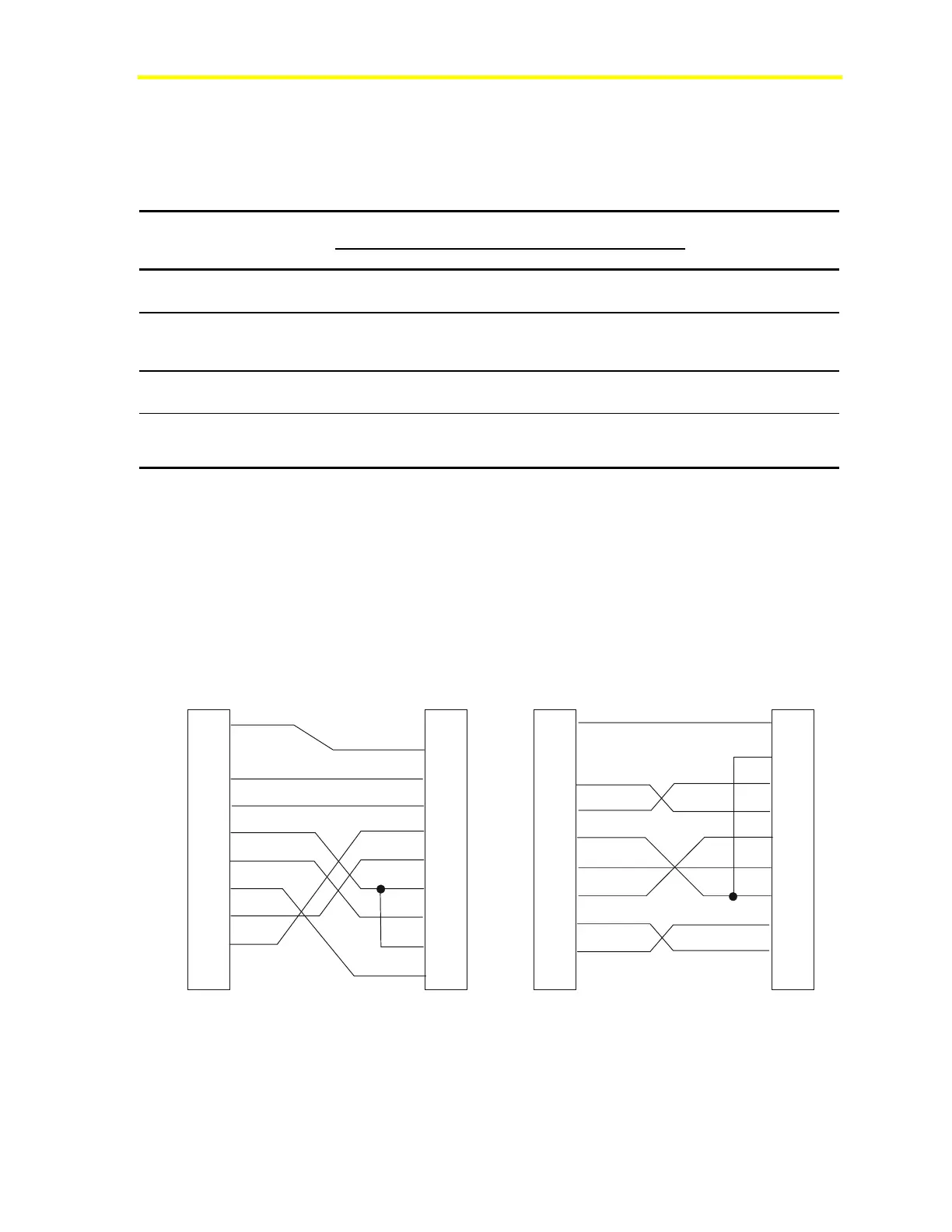
OWS Cabling
Figure 9 illustrates the NCM connections to either the 25-pin or 9-pin
OWS.
1
2
3
4
5
6
7
8
9
DCD
RD
TD
DTR
SG
DSR
RTS
CTS
NC
NCM
9-pin Female
1
2
3
4
5
6
7
8
20
PC Serial Port
25-pin Female
1
2
3
4
5
6
7
8
9
DCD
RD
TD
DTR
SG
DSR
RTS
CTS
NC
NCM
9-pin Female
1
2
3
4
5
6
7
8
9
PC Serial Port
9-pin Female
nc3fig7
Shell
Shell
Shell
DCD
RD
TD
DTR
SG
DSR
RTS
CTS
FG
TD
RD
RTS
CTS
DSR
SG
DCD
DTR
Figure 9: PC Serial Port of OWS Connected