PEAK® OEM 18 240 Volt SMART Equipment Controller Installation Instructions
20
Setup and Adjustments
Setting the Device Addresses
Use the local display or MAP Gateway to set up device addresses. PEAK® field controllers are master devices on
MS/TP
SA buses. Before operating field controllers on a bus, you must set a valid and unique device address for
each controller on the bus through the local display or MAP gateway. Device addresses 4 through 127 are the valid
addresses for these controllers.
Refer to the MS/TP Communications Bus Technical Bulletin (LIT-12011034) for more information on field controller
device addresses and how to set them on MS/TP buses.
24~ OUT 24~ 24 VAC Utility Supply (for actuators) - 125 mA
continuous, 250 mA peak for up to 120 seconds.
0.8 mm to 1.5 mm
2
(18 AWG) 2-wire
COM 24 VAC Power Supply Common
MOD BUS + Modbus communications 0.6 mm (22 AWG) stranded, 4-wire
(2 twisted pairs), shielded cable
recommended
-
COM Signal Reference (Common) for bus
communications
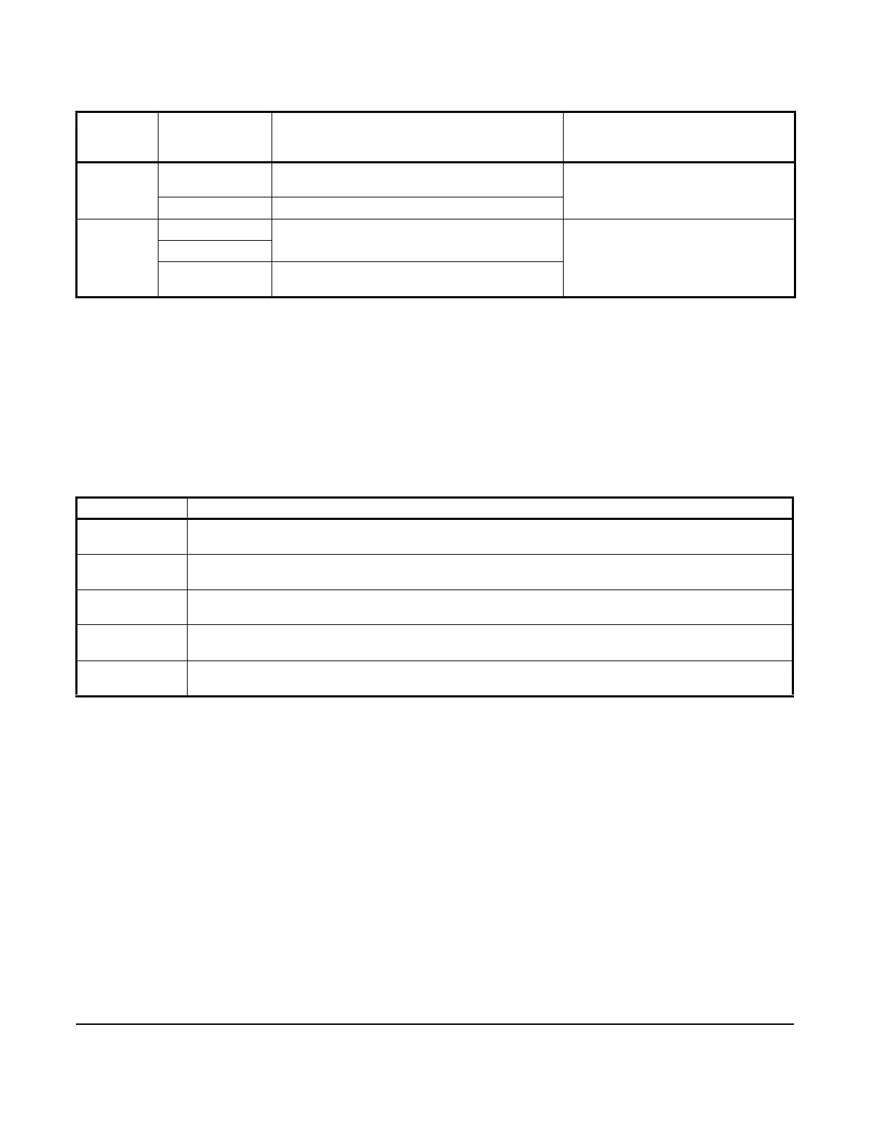
Table 6: SA Bus Device Address Description
Device Address Use on Description
0
(Switch 128 Off)
Reserved for FC Bus Supervisory Controller (not for use on field controllers).
1 to 3
(Switch 128 Off)
Reserved for peripheral devices (not for use on field controllers).
4 to 127
(Switch 128 Off)
Used for MS/TP master devices (field controllers) that are hardwired to an SA bus or FC bus.
0 to 3
(Switch 128 On)
Reserved addresses for wired slave devices (not for use on field controllers).
4 to 127
(Switch 128 On)
Valid for MS/TP Master field controllers on wireless FC Buses only (future).
Table 5: Communication Bus and Supply Power Terminal Blocks, Functions, Ratings, Requirements, and
Cables (Part 2 of 2)
Terminal
Block/Port
Label
Terminal Labels Function, Electrical Ratings/Requirements Recommended Cable Type
 Loading...