System 450™ Series Modular Control Systems with Standard Control Modules Technical Bulletin12
.
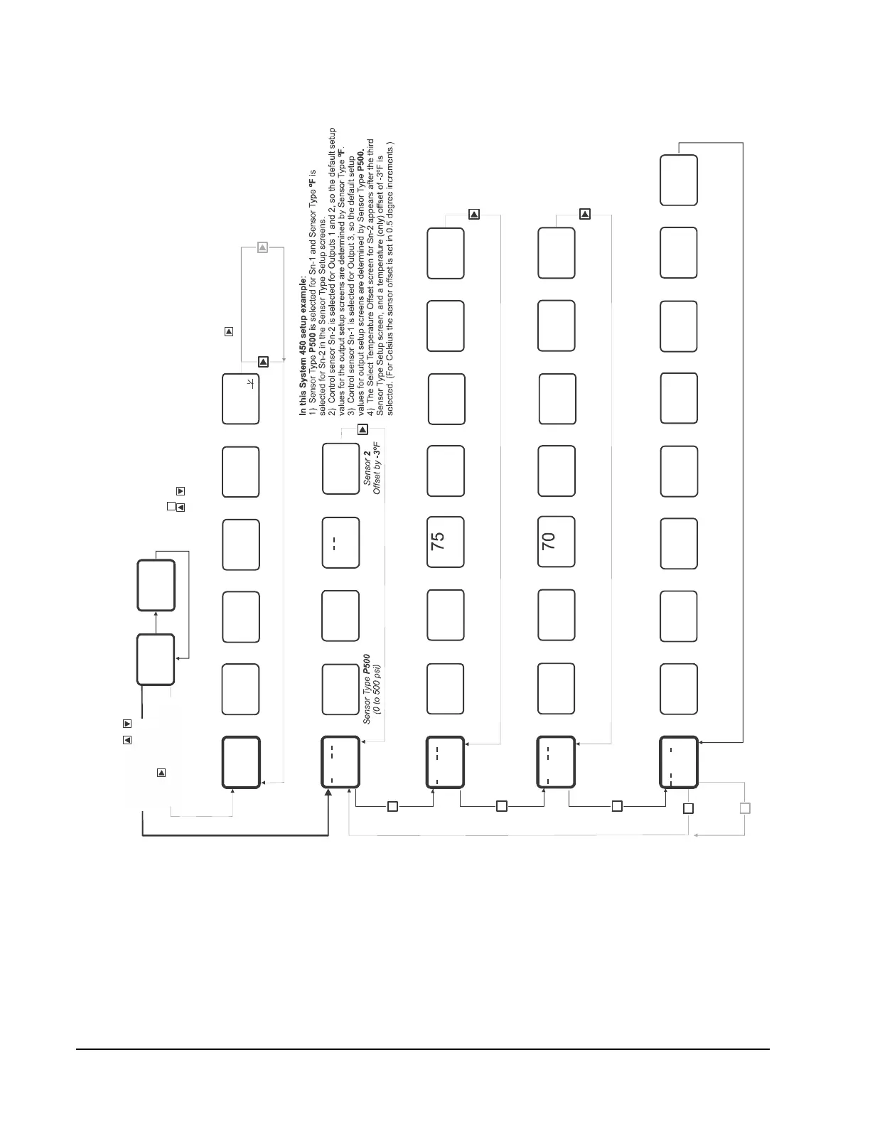
Figure 3: System 450 UI Menu Flow Chart Example Showing Navigation Paths and
Example Settings in the Main, System Status, Sensor Setup, and Output Setup Screens
for the Room Heating and Cooling Control System with Condenser Fan Speed Control
Application Shown in Figure 1
M
FIG:menu_flw_chrt
232
PSI
1
Main Screen
Sensor 2 Status
74
°F
2
Main Screen
Up to ten Outputs and
three Sensors can be
set up and displayed.
Relay Output 2
Status
OFF
OUT
2
Output Relay
2
OFF
Relay Output 1
Status
OUT
1
Output Relay
1
On
Analog Output
3
Status
64
OUT
3
Output Signal
ge
3
Sensor 3
Status
– – – –
3
Sensor
Not Set Up
3
Sensor 2
Status
74ºF
2
at Sensor
74
232
PSI
1
Sensor 1
Status
232 psi
1
at Sensor
Sensor Setup
Screens
System Status
Screens
Main Screens
(Sensor Status)
Relay Output 1
Cooling
Equipment
Setup Screens
Press and hold +
for 5 seconds to go to
the Setup Start screens.
Press to scroll through
Sensor Status screens and
Output Status screens.
SENS
Sensor Type
Setup Start
Select Sensor 2
Type
°F
Sensor Type
(-40 to 250ºF)
ºF
Select Sensor 3
Type
No
Sensor Type
Selected
Select Sensor 1
Type
P500
Sn-1
Sn-2 Sn-3
Select
Temperature (only)
Offset Degrees
-3
OFFS
2
During normal operation, the display automati
cally scrolls through the Sensor Status screens
for all sensors set up in the UI.
After a 2 minute pause in any setup or status
screen (below), the display returns to autoscrolling through the
Main (Sensor Status) screens.
Press in any Setup screen to go to the ass
ociated Setup Start screen.
Press + simultaneously in any Setup Sta
rt screen to return to autoscrolling through the Main screens.
M
On
°F
2
Relay Output
Setup Start
OUTR
1
Sensor 2
1
Selected for
Relay Output
Relay
Output
1
Select Relay ON
Value
ON
1
78
Relay Output
at ºF
1
ON 78
OFF
1
Select Relay OFF
Value
Relay Output
at ºF
1
OFF 75
Select Minimum
Relay ON Time
ONT
1
0
Relay Output
Seconds
(Minimum)
1
ON 0
Select Sensor
Failure Mode
SNF
1
OFF
Relay Output
if
Sensor 2 Fails
1
OFF
lect Minimum
lay OFF Time
OFFT
1
120
elay Output
Seconds
(Minimum)
1
F 120
Edit
Input Sensor
Sensor (Sn-2)
Controls
Relay Output
2
1
SENS
1
Sn-2
Up to ten
Outputs can
be connected
and set up.
M
OUTA
3
OutputAnalog
Setup Start
Analog
Output
3
Select
Setpoint Value
Prop. Band
SP
3
200
Analog Output
Prop. Band
Setpoint psi
3
200
Select Prop. Band
End Point Value
EP
3
250
Analog Output
Prop. Band
End Point psi
3
250
Select Integration
Constant Value
I-C
3
0
Analog Output
Integration
Constant
3
No
Select % Output
Signal Value
at Setpoint
OSP
3
10
Output is %
of Range at
Value
10
Setpoint
Select % Output
Signal Value
at End Point
OEP
3
90
Output is %
of Range at
Value
90
End Point
Select Sensor
Failure Mode
SNF
3
OFF
Analog Output
if
Sensor 1 Fails
3
OFF
M
Analog Output 3
Condenser
Fan Speed
Control
Setup Screens
M
SENS
3
Edit
Input Sensor
Sensor (Sn-1)
Controls
Analog Output
1
3
Sn-1
Select
Sensor
SENS
3
Sensor 1
3
Selected for
Analog Output
Sn-1
Relay Output
Setup Start
OUTR
2
Sensor 2
2
Selected for
Relay Output
Relay
Output
2
Select Relay ON
Value
ON
2
Relay Output
at ºF
2
ON 65
OFF
2
Select Relay O
FF
ut
ºF
2
0
Select Minimum
Relay ON Time
ONT
2
0
Relay Output
Seconds
(Minimum)
2
ON 0
Select Sensor
Failure Mode
SNF
2
OFF
Relay Output
if
Sensor 2 Fails
2
OFF
Select Minimum
Relay OFF Time
OFFT
2
30
Relay Output
Seconds
(Minimum)
2
OFF 30
Edit
Input Sensor
Sensor (Sn-2)
Controls Relay
2
2
SENS
2
Sn-2
The current status of each sensor and output is displayed.
Press to manually scroll through the sensor and output statuses.
Relay Output 2
Heating
Equipment
Setup Screens
65

 Loading...


