System 450™ Series Modular Control Systems with Standard Control Modules Technical Bulletin30
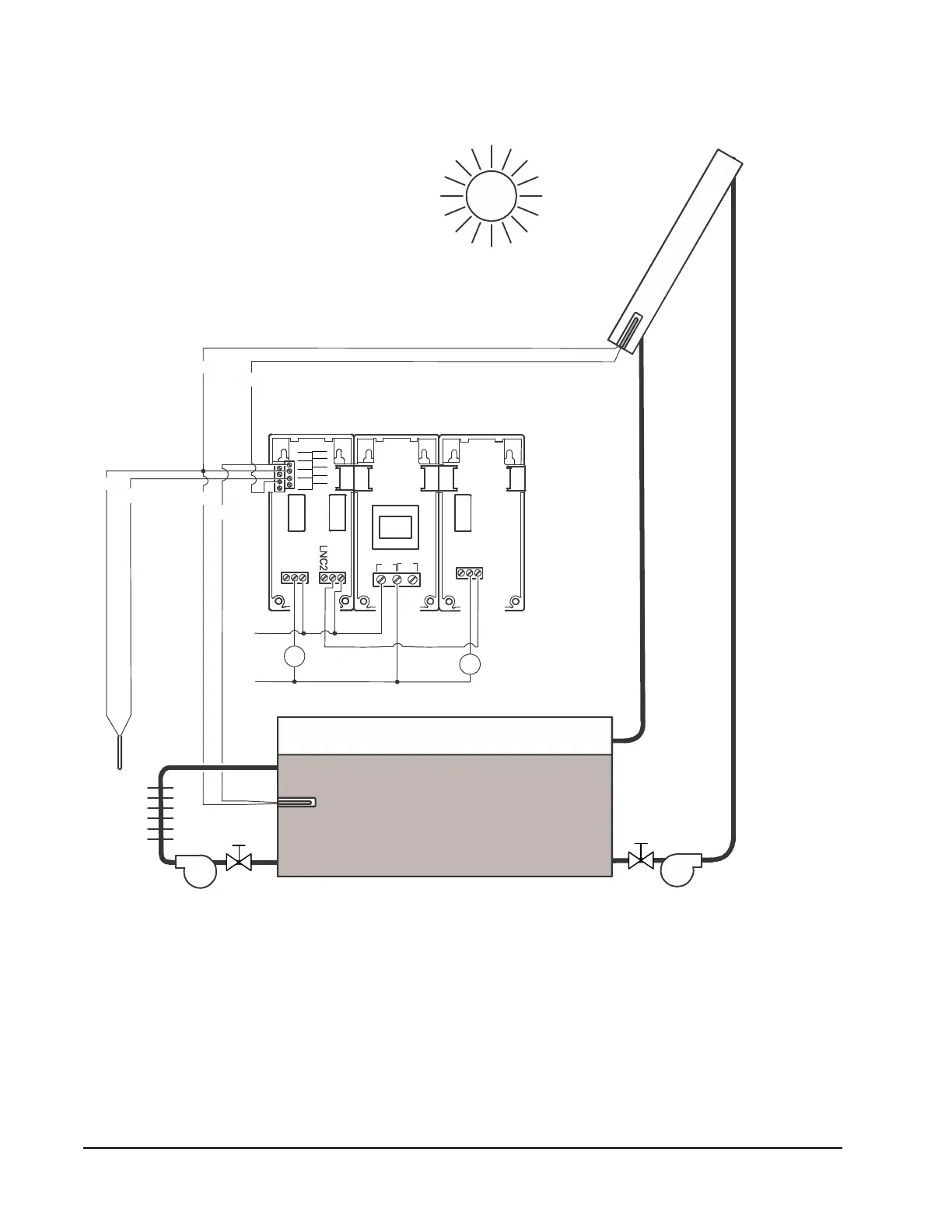
Figure 12 shows the System 450 UI Main screens, System Status screens, and
System Setup screens for the control system shown in Figure 11.
Figure 11: Solar Water Space Heating Control System Example That Uses
the Differential Control Feature
LC1
O1
NC1
WIRI NG
24V
Sn2
C
C
C
Sn1
Sn3
5V
LC1
LNO1
LNC1
LC2
LNO2
LC1
LNO1
LNC1
LC2
LNO2
Room
Heating
Loop
Room
Sensor
Sn3
Solar Panel
Sensor
Sn1
C
C
C
Sn3
L1
Room Heating
Circulation Pump
So
l
a
r
C
o
l
l
e
c
t
o
r
L2
Control Module
OUTR1, OUTR2
C450YNN-1C
Power Module
C450SBN-x
Expansion
Module
OUTR3
Solar Panel
Circulation Pump
C1
C2
C2
C1
Solar Water
Storage
Storage
Ta nk
Sensor
Sn2
Sn1
FIG:Sys450_solar_diffcontrol_diagram

 Loading...


