System 450™ Series Modular Control Systems with Standard Control Modules Technical Bulletin 39
Table 6 provides descriptions, ratings, requirements, and recommended cable
types and recommended wire sizes for System 450 standard control, expansion,
and power modules.
Table 6: System 450 Wiring Terminal and Wire Size Information (Part 1 of 2)
Terminal Block
Type
(on Module Type)
Terminal
Label
Terminal Function Required Wire
Sizes
Sensor and
Low-Voltage
Supply Power
Terminal Block
(on all Control
Modules)
24V Accepts 24 VAC supply power, when a
C450YNN-1C power module is not connected, and
provides power terminal for active 24 VAC (humidity)
sensors.
28 AWG to 16 AWG
0.08 mm
2
to 1.5 mm
2
5V Provides 5 VDC power for active sensors.
Sn1, Sn2,
Sn3
Accepts passive or active input signals from
sensors.
C
(3
Terminals)
Provides low-voltage common connections for
24 VAC power and passive or active sensors
connected to the 5V, Sn1, Sn2, and Sn3 terminals.
Note: The three C terminals are connected
internally.
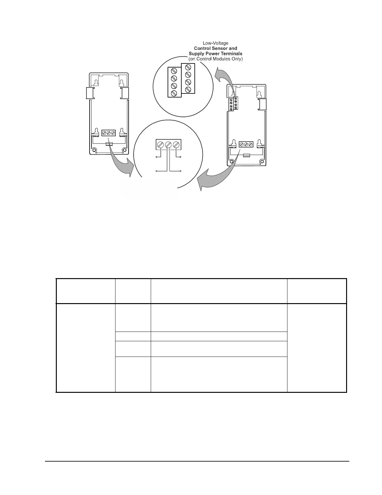
Figure 16: Wiring Terminal Details for System 450 Control and
Expansion Modules with Analog Outputs
System 450
Control Module
with Analog Outputs
(C450CQN-x)
System 450
Expansion Module
with Analog Outputs
(C450SQN-x)
sys450_anlg_cntrl_expnsn_wirng
AO2
COM
AO1
Analog
Controlled
Device
Analog
Controlled
Device
+
__
+
Low-Voltage
(on Analog Control and
Analog Expansion Modules)
Sn2
Sn3
5V
24V
C
Sn1
C
Common terminals (C)
are internally
connected.
AO2
COM
AO1
C450xPN-x control and expansion modules only have two terminals with AO1
and COM connections.

 Loading...


