System 450™ Series Modular Control Systems with Standard Control Modules Technical Bulletin 49
The Relay ON (ON
x
) screen and Relay OFF (OFF
x
) screen allow you to select
the condition values at which the relay turns on and turns off. The first time you
access the Relay ON (ON
x
) and Relay OFF (OFF
x
) screens, the default ON and
OFF values for the referenced sensor appear.
The minimum differential value for the condition is determined by the Sensor
Type of the sensor that an output references. The minimum differential is fixed and
is automatically enforced in the setup UI when you select ON and OFF values.
After you select the ON value, the condition values within the minimum
differential range are not available to select. See Table 5 for minimum differential
ranges.
The Minimum Relay ON Time (ONT
x
) and Minimum Relay OFF Time
(OFFT
x
) screens provide anti-short-cycling control for system equipment by
allowing you to delay the shutdown or startup for up to 300 seconds (5 minutes)
after the ON or OFF value is reached.
The Sensor Failure Mode (SNF
x
) screen allows you to select whether the output
relay is on or off if the referenced sensor encounters a sensor or wiring failure. See
Sensor Failure Mode on page 26 for more information.
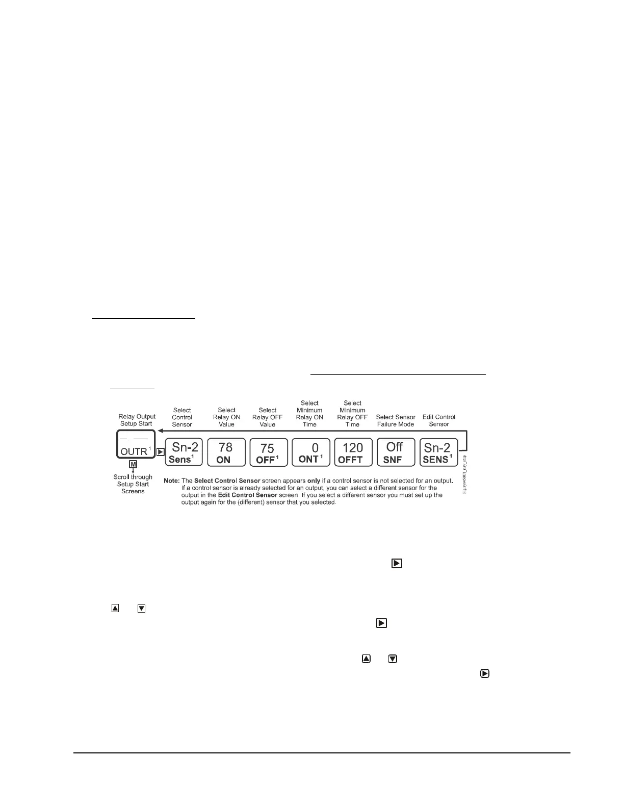
To set up a relay output:
1. Access the System 450 UI and navigate to the desired Relay Output Setup
Start (OUTR
x
) screen (Figure 22). (See Accessing and Navigating the User
Interface on page 42.)
2. In the Relay Output Setup Start (OUTR
x
) screen, press to go to the Select
Sensor (SENS
x
) screen. (The Select Sensor screen does not appear here if the
sensor is already selected for this output. In that case, go to the next step.) Press
or to select the hard-wired or functional sensor (Sn-1, Sn-2, Sn-3, Sn-d,
HI-2, or HI-3) you want the output to reference. Press to save the sensor
selection and go to the next screen.
3. In the Select Relay ON Value (ON
x
) screen, press or to select the
temperature, pressure, or humidity value at which the relay turns On. Press
to save the ON value and go to the next screen.
Figure 22: Relay Output Setup Start Screen and Setup Screen Flow

 Loading...


