System 450™ Series Modular Control Systems with Standard Control Modules Technical Bulletin 51
When you supply power to a module assembly, the control module polls all of the
connected modules, detects all of the outputs in the module assembly, then assigns
an output number to each output, and enables an Analog Output Setup Start
(OUTA
x
) screen for each analog output detected (Figure 25 on page 52). See
Analog Outputs on page 20 for more information.
Note: The condition (temperature, pressure, or humidity), unit of measurement,
minimum differential value, default setup values, and condition value
ranges available in the output setup screens are determined by the Sensor
Type of the sensor that you select for the output. See Table 2 on page 16 for
more information on sensors that are compatible with System 450 standard
control modules, their Sensor Types, and the values and ranges associated
with each Sensor Type.
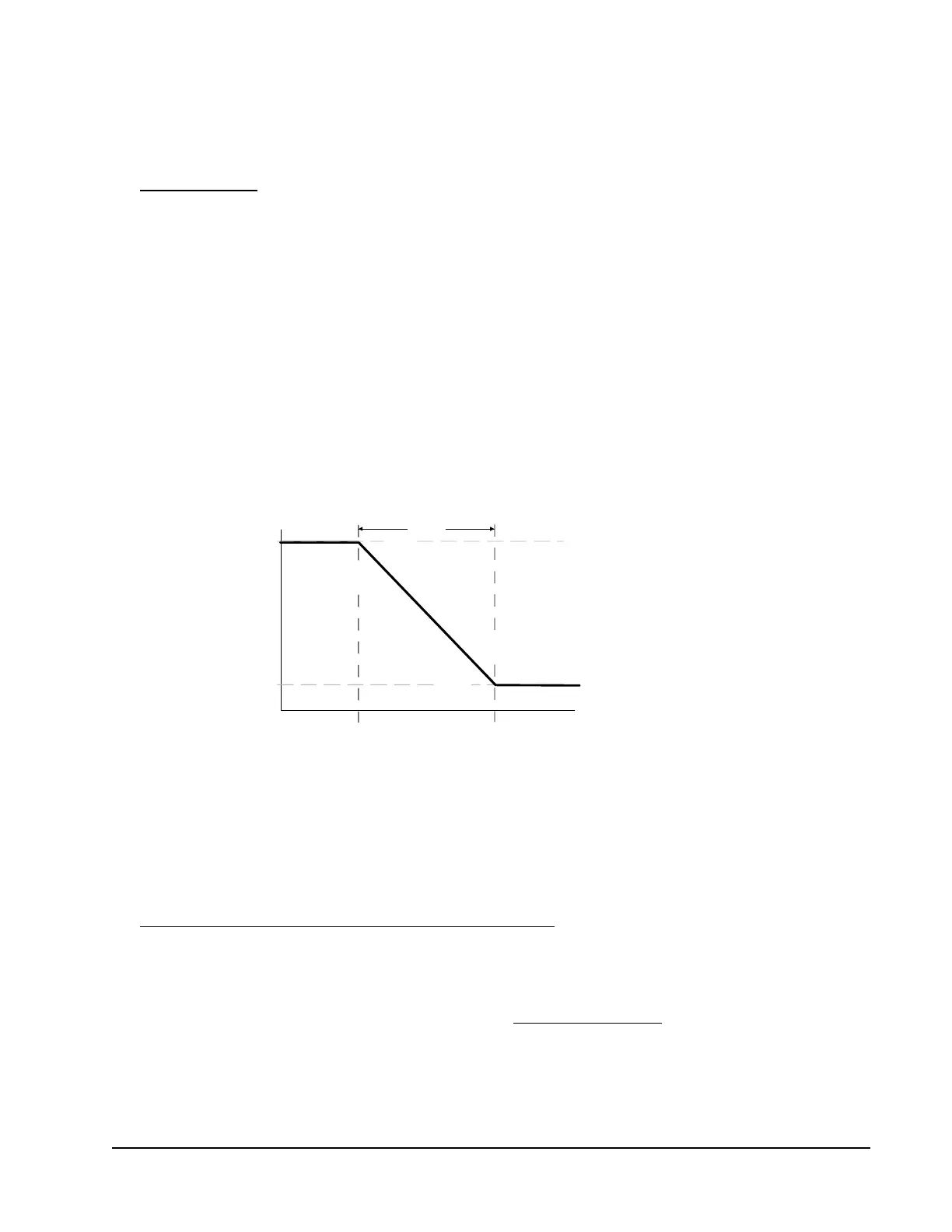
The Setpoint (SP) and End Point (EP) screens allow you to set up a proportional
band (or throttling range) for the control loops in your controlled system.
The Output at Setpoint (OSP) and Output at End Point (OEP) screens allow
you to select the output signal strength (as a percentage of the total signal strength
range) that an analog output sends to the controlled equipment at Setpoint and End
Point.
The relationship between these four setup values (SP, EP, OSP, and OEP)
determines the analog output’s proportional control action, which is indicated on
the control module LCD by the control ramp indicator. See Figure 2 on page 10
Direct and Reverse Control Actions for Analog Outputs
on page 20 for more
information.
Note: System 450 analog outputs that reference the differential control sensor
(Sn-d) use a Differential Setpoint (dSP) and Differential End Point (dEP) to
define the output’s proportional band. See Differential Control
on page 25
for more information.
Figure 23: Relationship between Setpoint, End Point, Output at Setpoint,
and Output at End Point for an Analog Output That Controls Room Heating
Condition Value
OSP
SP
EP
Sensor Type =
= 70 ( )
= 65 ( )
>
= 10 (%)
= 100 (%)
SP
EP
SP EP
OSP
OEP
°F
°F
°F
Proportional
Band
Fig:sys450_cntrl_rmp_1

 Loading...


