System 450™ Series Modular Control Systems with Standard Control Modules Technical Bulletin52
The Integration Constant (I-C) screen allows you to select an integration
constant for the analog signal. Selecting an integration constant other than 0
enables proportional plus integral control action, which in many applications can
drive the condition closer to setpoint (than proportional-only control action). See
Proportional Plus Integral Control and Integration Constants on page 23 for more
information. See Determining the Integration Constant for an Analog Output on
page 56 for procedures on determining and testing integration constants in your
control system.
The Sensor Failure Mode (SNF
x
) screen allows you to select whether the analog
output signal is off (corresponding to the lowest output capacity) or on
(corresponding to the highest output capacity) when a sensor failure is detected.
See Sensor Failure Mode on page 26 for more information.
To set up an analog output:
Note: In any of the system setup screens, press to return to the setup start
screen. In the setup start screen, press and simultaneously or wait two
minutes to return to the Main screens.
1. Access the System 450 UI and navigate to the desired Analog Output Setup
Start (OUTA
x
) screen (Figure 25). (See Accessing and Navigating the User
Interface on page 42 for information on accessing the System Setup screens.)
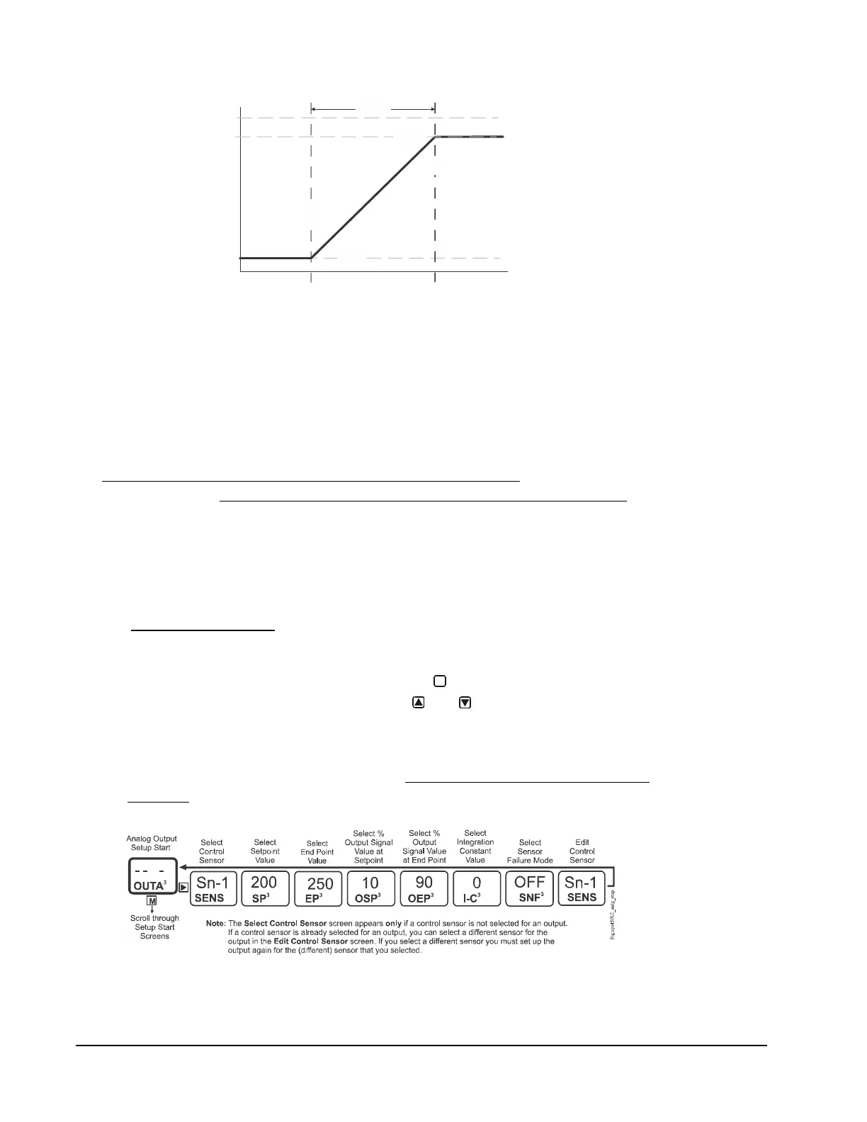
Figure 24: Relationship between Setpoint, End Point, Output at Setpoint, and
Output at End Point for an Analog Output That Controls Condenser Fan Speed
Condition Value
EP
Sensor Type =
= 20 (bar)
= 30 (bar)
<
= 5 (%)
= 90 (%)
P50
SP
EP
SP EP
OSP
OEP
OEP
Proportional
Band
Fig:sys450_cntrl_rmp_2
M
Figure 25: Analog Output Setup Start Screen and Setup Screen Flow

 Loading...


