Hardware Installation S300-DIN-RDR2S Module
4 24-10239-413 Rev. A
This document contains confidential and proprietary information of Johnson Controls, Inc.
© 2010 Johnson Controls, Inc.
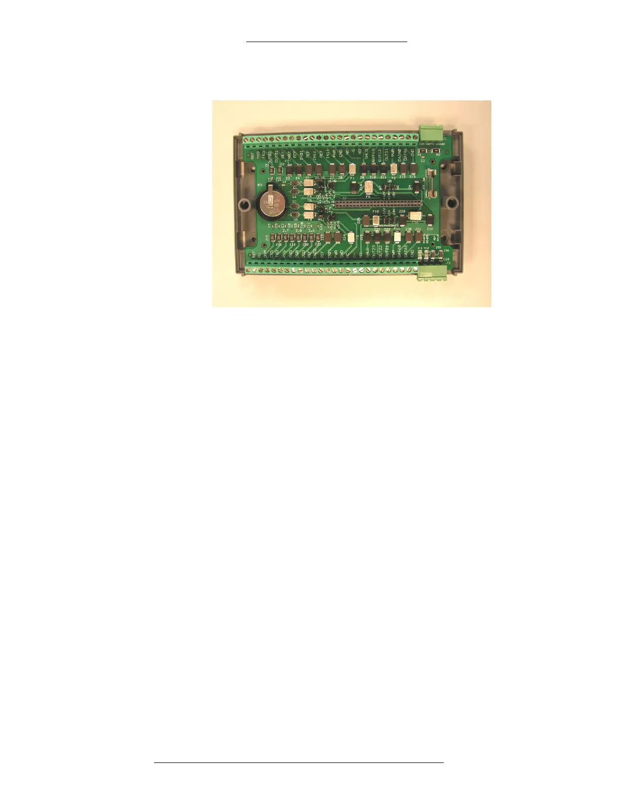
To separate the electronics board from the wiring base:
1. Unscrew the two screws holding the top and bottom parts of the enclosure.
2.
Separate the components.
T
o mate the electronics board to the wiring base:
1.
Using the guides, properly orient the electronics module.
2. Secure the top and bottom parts with the two screws.
Acceptable Switch/Relay Contacts
Important: Use only fine gold, gold flash, or reed switch/relay contacts. Do NOT
use silver, coin silver, or nickel contacts, as these may oxidize and degrade over
time, thereby causing the circuit to fail.
MOUNTING (NO ENCLOSURE)
The S300-DIN-RDR2S can be mounted on a flat surface, DIN rail, or in an S300-DIN
enclosure.
For information on mounting the S300-DIN-RDR2S in an S300-DIN enclosure, including
power information associated
with the S300-DIN-L-PS and S300-DIN-S-PS model power
supplies, refer to the S300-DIN-L Hardware Installation Manual and the S300-DIN-S
Hardware Installation Manual.

 Loading...


