S300-DIN-RDR2S Module Hardware Installation
24-10239-413 Rev. A 23
This document contains confidential and proprietary information of Johnson Controls, Inc.
© 2010 Johnson Controls, Inc.
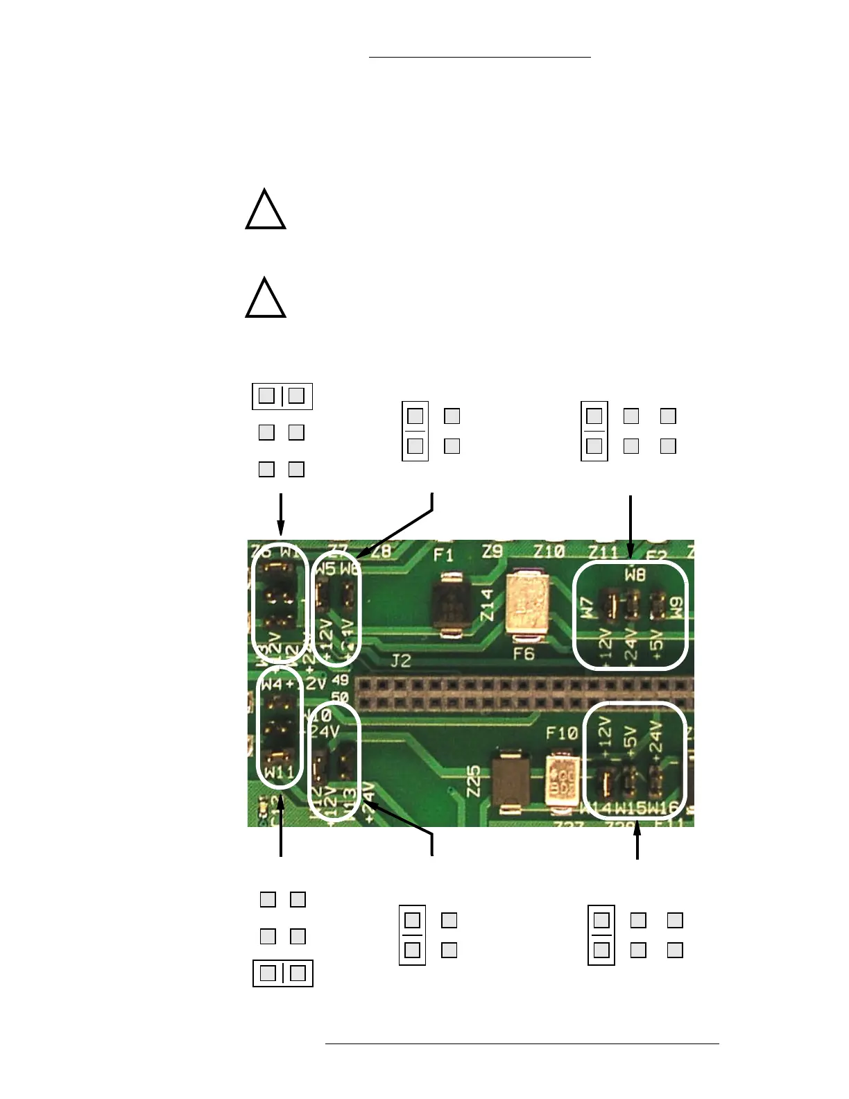
Configuration Jumpers
The following figure illustrates the positioning of configuration jumpers for reader
power, external devices (e.g. PIR), door strike, input points, and output points.
!
CAUTION
Read the silk screen carefully to select the correct reader power.
Incorrect selection may result in damage to the equipment.
!
CAUTION
One and only one jumper is allowed for each bank.
+12V +24V +5V
+12V +5V +24V
W14 W15 W16
W7 W8 W9
W1
W2
W3
+24V
+12V
W4
W10
W11
+12V
+24V
+12V +24V
W5 W6
+12V +24V
W12 W13
Reader Power: Door 1
Reader Power: Door 2
External Devices: Door 1
External Devices: Door 2
Door Strike: Door 1
Door Strike: Door 2
DRY
DRY

 Loading...


