GND
DAT+
DAT-
BLACK
WHITE
GREEN
RS485+
RS485-
REF
SHLD
YELLOW
RED
N/A
N/A
5
1
Wire nuts
Hardware Installation S300-DIN-RDR2S Module
12 24-10239-413 Rev. A
This document contains confidential and proprietary information of Johnson Controls, Inc.
© 2010 Johnson Controls, Inc.
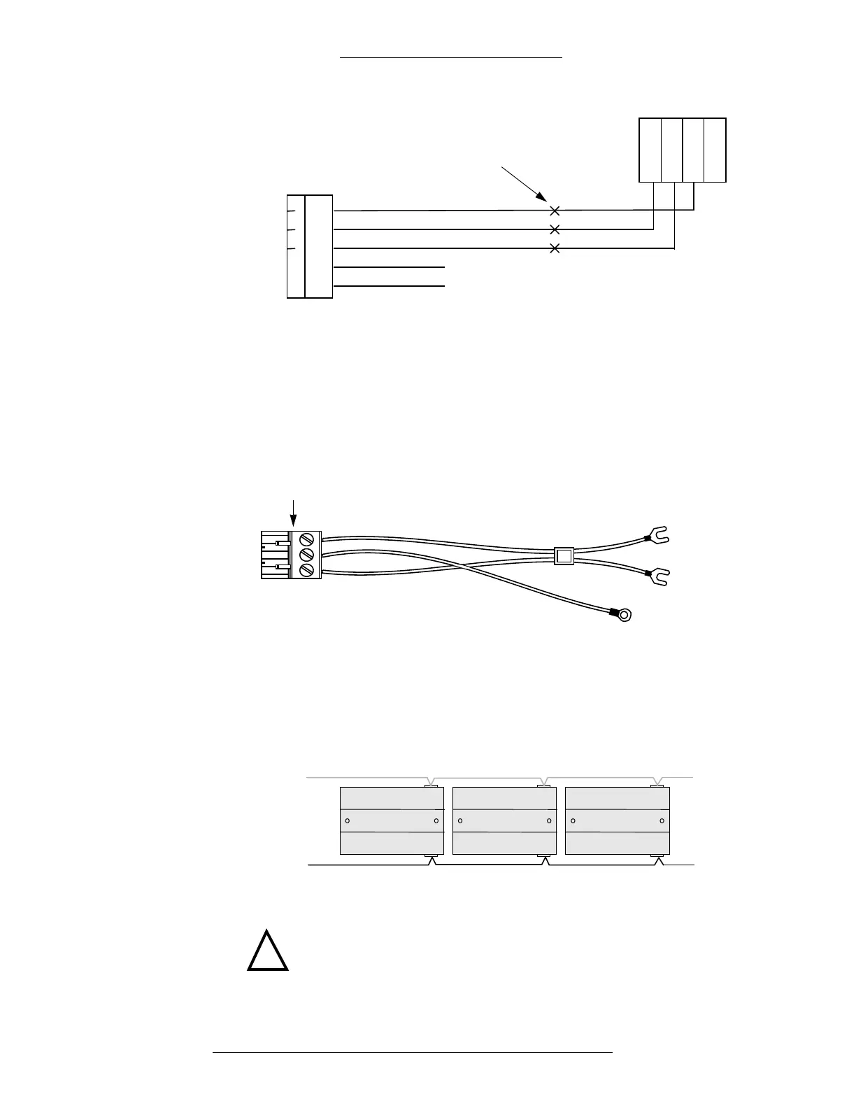
Power Supply
For power wiring with either the large or small enclosure, use the cable assembly
shown in the following figure. Refer also to the S300-DIN-L Hardware Installation
Manual and the S300-DIN-S Hardware Installation Manual.
Connects to
RDR2S module
Chassis
ground
COM
+24 VDC
connector
b
l
a
c
k
re
d
g
r
e
e
n
When connecting multiple RDR2S modules, wire the modules in parallel following
the “daisy chain” pattern as shown in the following figures. To construct the power
wiring, use listed 18 AWG wires.
1st RDR2S 3rd RDR2S2nd RDR2S
to the next
RDR2S
DC power cable
connecting to
power supply
RS-485 cable
connecting to
controller
!
CAUTION
Make sure each wire is connected to the same corresponding connector
position in the subsequent RDR2S module. See the following figure for
details.

 Loading...


