T500 Series Programmable Thermostats Product/Technical Bulletin
9
Single Stage
LED 1 Icon Off
LED 2 Icon Off
4 Events Per Day
Smart Fan Disabled
Heat/Cool: 4 Minute
(Minimum On)
Keyboard Unlocked
ON
1
3
2
4
5
6
2 Events Per Day
Smart Fan Enabled
Heat/Cool: 2 Minute
(Minimum On)
Keyboard Locked
7
8
LED 1 Icon
(Filter)
LED 2 Icon
(Wrench/Fault)
Multi-stage
Fan Immediate
with Heat Call
Fan On with
Plenum Switch
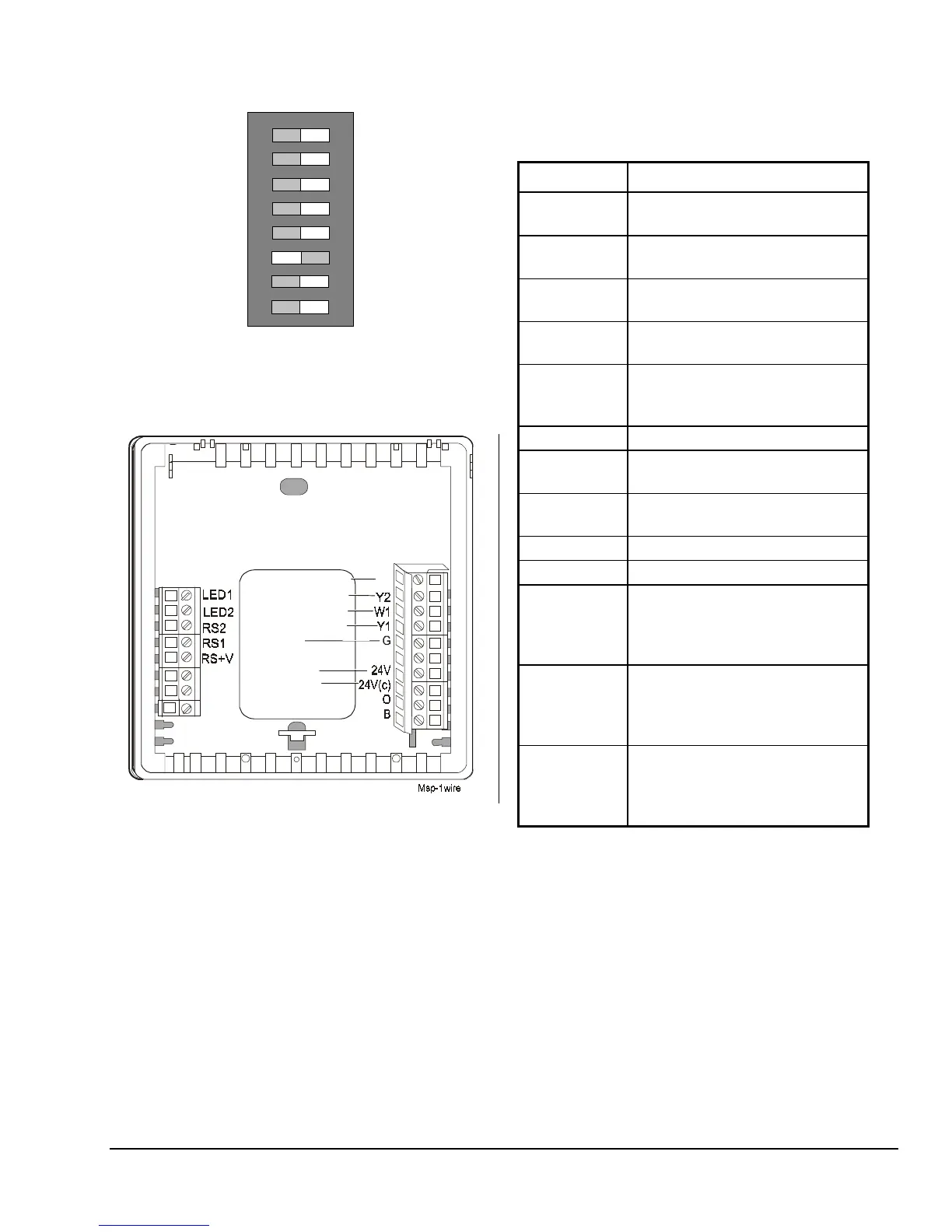
Figure 13: T500MSP-1 Factory Set
DIP Switch Settings
W2
R
NO
COM
NC
2nd Stage Heating
2nd Stage Cooling
1st Stage Heating
1st Stage Cooling
Fan
24VAC
Common
Figure 14: T500MSP-1 Wiring Terminals
Table 5: T500MSP-1 Output Terminal
Designations
Terminal Function
W2
Energizes on a call for
second-stage heat
Y2
Energizes on a call for
second-stage cooling
W1
Energizes on a call for first-stage
heat
Y1
Energizes on a call for first stage
cooling
G
Energizes fan on call for heating or
cooling or by pressing the
Fan
button
R
Independent switching voltage
24V
24 VAC from equipment
transformer
24V(c)
24 VAC (common) from equipment
transformer
O
Energizes in the cooling mode
B
Energizes in the heating mode
LED 1
LED 2
Input connection that energizes
LED 1 or LED 2 from remote status
device (See Figure 13 and
Table 6.)
RS2
RS1
RS+V
Connections for outdoor air
temperature or indoor remote
sensors; refer to instructions
included with sensors
NO
COM
NC
The relay coil is de-energized in the
night event. In all other events, the
relay coil is energized. (See
Figure 18.)
 Loading...